
Drinking Water Treatment Equipment Process Flow: From Raw Water to Bottled Output
Who This Guide Is For
Procurement managers, plant engineers, and project leads in beverage, food & beverage, pharmaceutical, and electronics manufacturing — especially those evaluating or specifying water treatment systems for bottled or barrelled drinking water production. You need clarity on how equipment stages interconnect, why certain configurations are chosen for specific water sources, and what constraints define feasibility — not generic diagrams.
Core Process Flow: Four Interdependent Stages
Chuxin Mingwei designs drinking water treatment systems as integrated, site-adapted sequences — not isolated units. The standard flow follows four functional stages, each with defined inputs, outputs, and engineering boundaries:
1. Pre-Treatment (Source Conditioning)
- Purpose: Remove suspended solids, chlorine, organic matter, hardness, and particulates that would foul downstream membranes or affect taste/safety.
- Typical configuration: Multi-media filter → activated carbon filter → softener (if hardness > 150 ppm) → 5 µmSecurity filter.
- Boundary note: As stated in our knowledge base, "pre-treatment must be calibrated to the original water report — no fixed configuration applies across groundwater, spring water, or municipal supply." For example, high-iron spring water requires manganese greensand or air-assisted oxidation; high-turbidity surface water demands dual-media + backwash optimization.
2. Primary Purification (Target-Specific Separation)
- Purpose: Achieve final dissolved solids, microbial, and mineral profile targets — determined by product type (purified vs. mineral water) and regulatory standards (e.g., GB 5749, USP <1231>, ISO 22000).
- Two distinct paths:
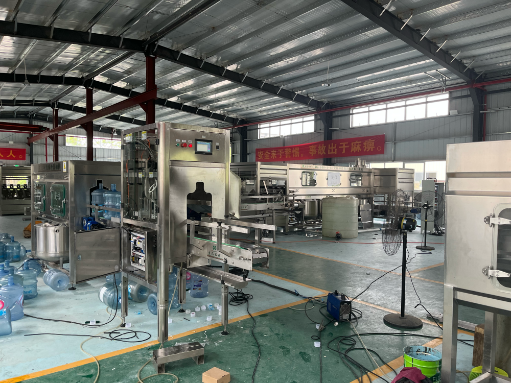
- Purified water: Dual-stage RO system (as used in our Fully Automatic Bottled Purified Water Filling Line), targeting ≤ 10 µS/cm conductivity. Includes high-pressure pump, membrane array, permeate storage, and reject recovery loop.
- Mineral/spring water: NF + UF hybrid system (featured in our Bottled Spring Water Filling Line), designed to retain Ca²⁺, Mg²⁺, and HCO₃⁻ while removing bacteria, viruses, and turbidity. No desalination — only selective separation.
- Boundary note: “Mineral retention is not optional — it’s engineered,” per our product documentation. Over-purification invalidates product classification and requires reformulation.
3. Disinfection & Storage (Microbial Safety & Stability)
- Purpose: Ensure microbiological safety at point-of-fill and prevent regrowth during storage/transfer.
- Standard configuration: Ozone generator + contact tank (0.2–0.4 mg/L residual) → UV sterilizer (254 nm, ≥ 40 mJ/cm² dose) → sterile stainless steel finished water tank with sanitary vent and CIP loop.
- Boundary note: As noted in our service knowledge base, “UV alone is insufficient for distribution loops — ozone provides residual protection; both are required for SC-compliant barrelled water lines.”
4. Distribution & Filling Interface (Hygienic Delivery)
- Purpose: Deliver treated water to filling machines without recontamination, pressure loss, or stagnation.
- Configuration: Constant-speed booster pump → sanitary 316L piping → flow meters, pressure transmitters, and temperature sensors → dedicated fill headers with drip prevention and auto-flush.
- Critical boundary: “Flow velocity must exceed 1.2 m/s in all loops to avoid biofilm formation,” per our engineering guidelines. Lower velocity requires enhanced CIP frequency and monitoring — a trade-off affecting OPEX.
Why 'One-Size-Fits-All' Doesn’t Apply
Our 16 years of field experience show that process flow isn’t transferable between sites — even with identical capacity or bottle size. A 2,000-bph purified water line in Guangdong uses different pre-treatment than an identical-capacity line in Xinjiang due to TDS variance (280 vs. 1,200 ppm). Likewise, a spring water line serving export markets must include additional UV validation and logbook-ready instrumentation — beyond domestic requirements.
Next Step: Get Your Site-Specific Flow Diagram
We don’t provide generic schematics. Instead, we build your process flow from your actual source water test report, target standard, hourly output, and facility layout. Submit your details via our Solution Consultation form, and within 3 business days, you’ll receive:
- A validated P&ID-style process flow diagram
- Equipment list with model-level specifications (e.g., membrane type, pump curve, UV lamp wattage)
- Preliminary footprint and utility load summary (power, compressed air, drainage)
- Clear scope boundaries: what’s included in delivery, commissioning, and first-year support.
This is how Chuxin Mingwei delivers stability, applicability, and long-term maintainability — not just hardware.