
Drinking Water Production Equipment Process Flow: From Source to Filled Bottle — A Technical Breakdown for Beverage & Ph
Who This Applies To
This process flow explanation is designed for procurement managers, plant engineers, and digital project leads evaluating or commissioning bottled water production lines in beverage, food, pharmaceutical, and electronics manufacturing facilities — especially those sourcing from variable spring sources or requiring ISO-class cleanroom integration.
Why Standardized Flow Charts Fall Short
Generic process diagrams (e.g., "pre-treatment → RO → storage → filling") misrepresent real-world execution. At Chuxin Mingwei, every production line starts not with a template — but with your source water quality report, target product standard (GB 19298, USP <1231>, or client-spec), packaging format (18.9 L PET, 5 L HDPE), hourly capacity (200–2,500 bph), and facility constraints (ceiling height, floor load, utility routing). The resulting process flow is non-standard, engineered per project.
Stage-by-Stage Process Flow — With Equipment Logic & Boundaries
1. Raw Water Intake & Pre-Treatment
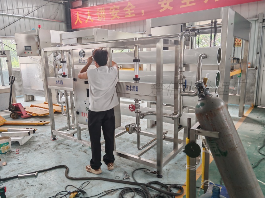
- Purpose: Remove coarse particulates, iron/manganese, organic load, and chlorine (if municipal supply).
- Chuxin Mingwei implementation: Multi-media filtration + activated carbon + precision cartridge filter (5 µm). For spring water, this stage avoids over-removal — preserving natural mineral profile while meeting downstream membrane protection requirements .
- Boundary note: Pre-treatment design is validated against actual lab-tested source water — not assumed turbidity or hardness ranges.
2. Core Purification — Matched to Product Type
- For purified water (e.g., GB 17323): Dual-stage RO system with ≥99.5% salt rejection, followed by ozone + UV (254 nm) sterilization (Product #59). RO is never isolated — it’s integrated with pre
- and post-conditioning to stabilize flux and extend membrane life.
- For spring/mineral water (e.g., GB 8537): NF + UF dual-membrane process — selectively retains Ca²⁺, Mg²⁺, and HCO₃⁻ while removing microbes and colloids (Product #60). No deep desalination; mineral retention is built into the membrane selection and operating pressure logic.
- Boundary note: Membrane type, staging, and recovery ratio are calculated per project — not selected from catalog tables.
3. Sterilization, Storage & Distribution
- Sterilization: Ozone injection (dose controlled via ORP feedback) + UV (254 nm, lamp intensity monitored in real time). UV alone is insufficient for residual control; ozone alone risks bromate formation — hence dual validation .
- Storage: Stainless steel 304/316 tanks with CIP-compatible internal surfaces, nitrogen blanketing option, and level/temperature/pressure monitoring.
- Distribution: Constant recirculation loop with sanitary diaphragm pumps and online conductivity/pH sensors.
4. Container Handling & Filling
- Bottle handling: Integrated bottle washing-filling-capping unit (Product #60, #59). Empty bottles undergo multi-stage rinse (pre-wash → alkaline wash → final rinse with purified water), then filled under laminar airflow.
- Filling accuracy: ≤ ±2 mL for 18.9 L bottles; capping pass rate ≥99.6% (verified during commissioning). PLC-based synchronization prevents cross-contamination between stages.
- Boundary note: Bottle compatibility is confirmed before
- mechanical design — including neck thread geometry, base stability, and thermal deformation tolerance.
5. Cleanroom Integration (Optional but Critical)
- Scope: Air purification systems engineered to ISO 14644-1 Class 8 (100,000) — upgradable to Class 7 (10,000) — with H13 HEPA filtration, real-time pressure zoning, and PLC+HMI diagnostics (Product #58).
- Integration logic: Airflow volume (1,500–20,000 m³/h) and duct routing are modeled to your building layout — not added as an afterthought.
Key Implementation Checkpoints
- Source water test report must be provided before
- process flow finalization.
- Bottling format (material, size, cap type) must be locked before mechanical design begins.
- No “one-size-fits-all” purification module — RO/NF/UF selection requires full water chemistry analysis.
- Cleanroom air system cannot be retrofitted post-line installation without structural review.
Next Step: Validate Your Flow
Chuxin Mingwei does not sell off-the-shelf lines. To receive a technically validated process flow diagram — with equipment list, utility specs, footprint layout, and commissioning protocol — submit your source water report and production requirements via our drinking water treatment equipment process flow inquiry form.