
Ultrafiltration Equipment Process Flow Explained: Key Stages, Configuration Logic, and Operational Boundaries
Ultrafiltration (UF) is often positioned as a standalone purification step, but in practice, it functions as part of a broader water treatment chain. For procurement managers and engineering teams planning beverage, food, pharmaceutical, or electronics facility projects, understanding the UF equipment process flow is essential for accurate capacity planning, realistic budgeting, and long-term operational stability.
This guide explains how UF systems are typically configured, where they sit in the overall treatment sequence, and what operational boundaries teams should plan for before procurement.
1. Where UF Fits in the Treatment Chain
Ultrafiltration does not replace pretreatment or final disinfection. It primarily targets suspended solids, colloids, turbidity, and certain microorganisms, while allowing dissolved minerals and salts to pass through. In packaged drinking water and industrial water projects, UF is commonly applied in two contexts:
- Mineral or spring water retention: When the source water contains beneficial minerals that must be preserved, UF provides physical separation without altering ionic composition.
- RO pretreatment or polishing: In purified water lines, UF can reduce SDI (Silt Density Index) and protect downstream RO membranes from fouling.
The decision to use UF depends on raw water quality, target water standards, and packaging format — not on equipment preference alone.
2. Typical Ultrafiltration Equipment Process Flow
A functional UF system follows a structured sequence. Each stage has specific engineering requirements and interfaces with upstream and downstream units.
2.1 Raw Water Intake and Preliminary Screening
Raw water enters through a coarse screen or strainer to remove large debris, sand, and organic matter. This step protects pumps and prevents sudden pressure spikes in the UF module.
2.2 Pretreatment and Conditioning
Depending on source water characteristics, pretreatment may include:
- Multi-media filtration to reduce turbidity
- Activated carbon filtration for chlorine and organic removal
- Softening or antiscalant dosing if hardness or scaling potential is high
Pretreatment is not optional; it determines membrane lifespan and cleaning frequency. Systems designed without proper conditioning often experience rapid flux decline and higher operational costs.
2.3 Ultrafiltration Module Operation
UF membranes operate under low to moderate pressure, typically driven by feed pumps. The process flow includes:
- Filtration phase: Water passes through membrane pores, retaining particles and microorganisms.
- Backwash cycle: Periodic reverse flow removes accumulated material from the membrane surface.
- Chemical cleaning (CIP): Scheduled cleaning restores flux when pressure differential or output quality degrades.
Membrane selection (material, pore size, module type) must align with water chemistry and production rhythm. There is no universal UF configuration; each system is sized based on actual flow requirements and fouling potential.
2.4 Post-Treatment and Disinfection
UF does not provide residual disinfection. Finished water typically requires:
- UV sterilization or ozone treatment for microbial control
- Secure storage in closed, food-grade tanks
- Hygienic piping and circulation loops to prevent secondary contamination
In bottling and barrelled water lines, UF-treated water must integrate with cleanroom environments and filling equipment to maintain product integrity.
3. System Configuration and Integration Considerations
UF equipment is rarely deployed in isolation. Practical projects require coordination across multiple subsystems:
- Pump sizing and pressure control: Feed pumps must maintain stable flow without exceeding membrane pressure limits.
- Instrumentation and monitoring: Pressure gauges, flow meters, and differential pressure sensors enable early detection of fouling or blockage.
- Automation and control: PLC-based systems manage filtration cycles, backwash timing, and cleaning sequences, reducing manual intervention.
- Space and utility planning: UF skids require adequate clearance for maintenance, chemical storage, and drainage. Facility constraints directly influence equipment layout.
For beverage and food production lines, UF systems are often integrated with bottle washing, filling, and capping units. Clean air support and environmental controls further ensure that treated water remains stable through packaging.
4. Operational Boundaries and Risk Management
Understanding UF limitations is as important as knowing its capabilities. Common operational boundaries include:
- No dissolved salt removal: UF cannot reduce TDS, hardness, or heavy metals. If ion reduction is required, RO or ion exchange must follow.
- Fouling and cleaning dependency: Membrane performance degrades over time. Cleaning frequency depends on raw water quality, pretreatment effectiveness, and operating parameters.
- Temperature and pH sensitivity: Extreme conditions can damage membrane materials. Operating ranges must be verified against manufacturer specifications.
- Regulatory and hygiene compliance: Finished water quality depends on the entire chain — not just the UF unit. Storage, piping, and filling environment must meet applicable standards.
Procurement teams should request source water analysis, define target water parameters, and clarify maintenance responsibilities before finalizing equipment selection.
5. Next Steps for Project Planning
If your team is evaluating UF for a new or upgraded water treatment line, consider the following actions:
- Conduct raw water testing: Identify turbidity, SDI, microbial load, and chemical composition.
- Define production requirements: Clarify capacity, packaging format, and facility constraints.
- Map the full treatment chain: Ensure UF integrates logically with pretreatment, disinfection, and filling systems.
- Request a site-specific proposal: Avoid generic equipment lists; require engineering documentation that reflects your actual conditions.
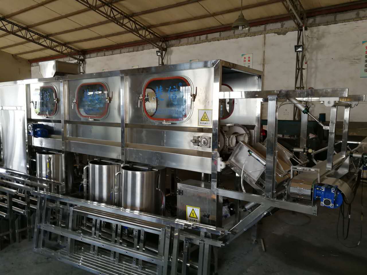
Chuxin Mingwei designs and manufactures custom water treatment systems, bottled and barrelled water filling lines, and clean air support solutions — delivered as end-to-end engineering services including design, manufacturing, installation, commissioning, operator training, and after-sales support. Each system is engineered from actual source water quality, target standards, production capacity, and facility layout.
For technical evaluation or project consultation, submit your water quality report and production requirements. Our engineering team will provide a site-specific process flow diagram and equipment configuration recommendation.