
Bottled Water Filling Machine Process Flow: From PET Preform to Palletized Output
Who This Process Flow Applies To
This guide is written for procurement managers, plant engineers, and operations leads evaluating or scaling a bottled water production line. It covers the standard process chain for disposable PET bottled water — from 330 mL single-serve formats up to 10 L large bottles — using integrated washing-filling-capping equipment and downstream packaging systems.
If your project involves returnable 5-gallon barrels, the process chain diverges significantly at the container-cleaning stage. This article focuses exclusively on one-way PET bottle lines.
The Standard Bottled Water Filling Process Chain
A complete bottled water filling line follows a sequential logic. Each stage depends on the output quality and timing of the previous one. The standard chain, as engineered and delivered by Chuxin Mingwei, runs as follows:
PET Preform → Blowing → Empty Bottle Conveying → Rinsing → Filling → Capping → Level/Cap Inspection → Drying → Labeling/Sleeve Labeling → Date Coding → Shrink Wrapping or Cartoning → Palletizing
Below is a stage-by-stage breakdown of the operating principles, equipment involved, and key decision variables.
Stage 1: Preform Handling and Bottle Blowing
The line begins with PET preforms — injection-molded test-tube-shaped blanks that are heated, stretched, and blown into finished bottles inside a blow-molding machine.
Operating logic: Preforms are fed into the blow molder, passed through an infrared heating oven to reach the target temperature profile, then transferred into molds where a two-stage blowing process (low-pressure pre-blow followed by high-pressure blow) forms the bottle against the mold cavity. Cooling water circulates through the mold to set the bottle shape before ejection.
Equipment involved:
- Semi-automatic or fully automatic blow-molding machines (configurations such as 1-out-2, 1-out-4, or 1-out-6 cavities)
- High-pressure air compressors, low-pressure air supply, refrigerated dryers, air filters
- Chiller units and mold sets for each bottle format
Key variables: Preform weight and grade, heating curve, stretch ratio, pre-blow/high-blow pressure timing, mold cooling efficiency, and compressed air quality all affect bottle wall-thickness uniformity, base clarity, and dimensional accuracy. Common defects include whitening at the base, uneven walls, off-center necks, and burst bottles during filling.
Boundary note: If your line sources pre-blown bottles from an external supplier, this stage is replaced by a bottle-unscrambling and air-conveying system. The downstream process remains the same.
Stage 2: Empty Bottle Conveying
Blown bottles exit the blow molder and must be transported to the filling monoblock. For lightweight PET bottles, air conveyors are the standard choice.
Operating logic: Bottles are suspended by their neck rings and propelled along enclosed stainless-steel guide rails by filtered, low-pressure air jets. This avoids contact with the bottle body and prevents contamination or deformation.
Key variables: Conveyor length, air pressure, guide-rail width adjustment for different bottle diameters, and the transition geometry into the rinsing-filling-capping monoblock. Mismatched air pressure or poorly adjusted rails cause bottle jams and neck damage.
Stage 3: Rinsing, Filling, and Capping — The Monoblock
This is the core of the entire line. A washing-filling-capping three-in-one machine integrates all three operations into a single, enclosed unit, minimizing intermediate transfer and exposure to ambient air.
Rinsing: Empty bottles are gripped by the neck, inverted 180°, and rinsed internally with filtered product water or sterile water to remove any residual dust or particles from the blowing stage. The bottles are then returned upright and transferred to the filling carousel.
Filling: Bottles are filled using gravity, micro-pressure, or volumetric filling valves depending on the water type and speed requirement. For purified and spring water at ambient temperature, gravity or micro-pressure filling is standard. The valve opens when the bottle is correctly positioned and seals when the target liquid level is reached.
Capping: Caps are sorted by an automatic cap sorter, disinfected (typically via UV or ozone water rinse), and fed to the capping heads. Each cap is placed onto the bottle and torqued to specification by magnetic or mechanical capping heads.
Equipment involved:
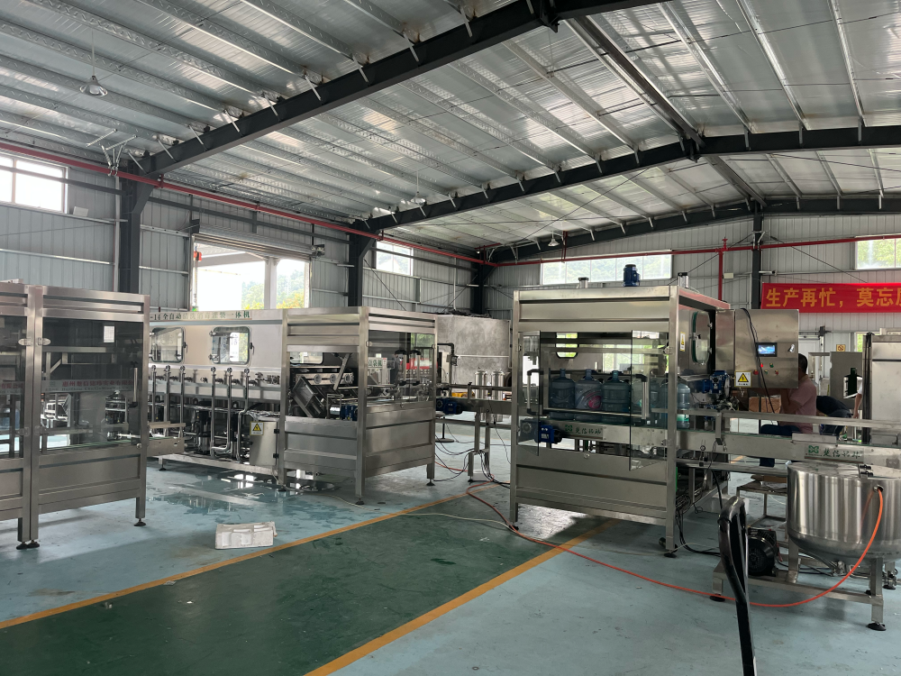
- Washing-filling-capping monoblock (3-in-1 integrated machine)
- Automatic cap sorter, cap elevator, cap disinfection unit
- PLC-based control with HMI interface
Key variables: Bottle diameter and height range, neck finish (e.g., 28 mm PCO or 30/25), target fill volume, rated output (bottles per hour), filling-valve type, and format changeover time. Actual line efficiency depends on upstream bottle supply stability and downstream conveyor synchronization — not just the monoblock's rated speed.
Boundary note: The monoblock's nameplate capacity is measured under ideal conditions with a single bottle format. Real-world throughput for lines running multiple SKUs with frequent changeovers will be lower. Capacity planning should account for format-switching frequency, cap-change time, and upstream/downstream buffer capacity.
Stage 4: Inspection — Level, Cap, and Visual
After capping, every bottle passes through a series of inline checks.
Level detection: Verifies that each bottle has been filled to the target volume. Under-filled or over-filled bottles are automatically rejected.
Cap inspection: Checks for missing caps, skewed caps, or improperly seated caps using photoelectric sensors or vision systems.
Visual/light inspection: Bottles pass through a light-inspection station (light box) where operators or cameras check for suspended particles, foreign objects, or bottle defects.
Key variables: Detection sensitivity, reject-mechanism speed, and the false-reject rate. Vision-based systems offer higher accuracy but require calibration for each bottle format and lighting condition.
Stage 5: Bottle Drying
Wet bottles cannot be labeled or coded reliably. A bottle dryer removes external moisture using high-velocity air knives or centrifugal blowers.
Operating logic: Bottles pass through a drying tunnel where angled air jets strip water from the bottle surface, with particular attention to the neck and shoulder areas where label adhesion is critical.
Key variables: Air-knife angle, blower power, conveyor speed, and ambient humidity. Inadequate drying causes label wrinkling, ink smearing, and sleeve-shrink defects.
Stage 6: Labeling and Date Coding
Labeling options:
- Pressure-sensitive (adhesive) labeling: A pre-printed label is peeled from a backing web and applied to the bottle. Suitable for premium branding and complex graphics.
- Shrink-sleeve labeling: A printed sleeve is dropped over the bottle and passed through a steam or hot-air shrink tunnel to conform to the bottle contour. Suitable for full-body coverage and tamper-evident designs.
Date coding: Laser or inkjet coders print the production date, batch number, and expiry information onto the cap or label.
Key variables: Label dimensions, application position, shrink-tunnel temperature profile (for sleeves), bottle shape compatibility, and coding legibility at line speed.
Stage 7: End-of-Line Packaging
Finished bottles are grouped and packed for distribution.
Shrink wrapping: Bottles are arranged in a matrix (e.g., 4×6 or 3×4), wrapped in PE shrink film, and passed through a heat tunnel to form a tight, stable pack. This is the most common format for bottled water.
Cartoning: Bottles are placed into corrugated cartons, which are then sealed by tape or hot-melt glue. Used for premium products or markets requiring additional protection.
Palletizing: Packs or cartons are stacked onto pallets in a programmed layer pattern. Automatic palletizers handle layer formation, slip-sheet insertion, and full-pallet discharge.
Key variables: Pack configuration, film thickness and shrink temperature, carton dimensions, pallet pattern, stacking height, and compatibility with warehouse racking and forklift routes.
Process Flow Decision Matrix
| Decision Point | Key Variables | Typical Range |
|---|---|---|
| Bottle format | Volume, neck finish, shape | 330 mL – 10 L |
| Blow-molding integration | In-house vs. outsourced preforms | 1-out-2 to 1-out-6 cavities |
| Filling method | Gravity, micro-pressure, volumetric | Ambient temperature for most drinking water |
| Line capacity | Rated vs. actual throughput | 2,000 – 24,000+ bottles/hour |
| Labeling type | Adhesive vs. shrink sleeve | Depends on branding and market |
| End-of-line pack | Shrink wrap vs. carton | PE film most common for water |
| Cleanroom requirement | Filling-zone air cleanliness | ISO Class 8 (100,000) typical for drinking water |
Operational Boundaries and Common Risks
1. Capacity is a system property, not a single-machine number. The monoblock, blow molder, labeler, and packer must be speed-matched. A bottleneck at any stage — often the labeler or shrink wrapper — caps the entire line's output.
2. Format changeover is a real cost. Lines running three or more bottle sizes need quick-change tooling, adjustable guide rails, and recipe-based PLC programs. Changeover time directly reduces available production hours.
3. Cleanroom discipline matters at the filling zone. The rinsing-filling-capping area should operate within a controlled environment. Air purification systems with HEPA filtration, positive pressure, and defined personnel/material flow paths reduce secondary contamination risk. Specific cleanroom class requirements depend on the product category and local regulatory standards.
4. Water quality upstream determines filling stability. The water treatment system — including multi-media filtration, activated carbon, reverse osmosis or ultrafiltration, and final disinfection via ozone or UV — must deliver consistent quality to the filling monoblock. Fluctuations in conductivity, microbial load, or particulate count will manifest as filling defects or product-quality failures.
5. Maintenance is condition-based, not calendar-based. Consumables such as filling-valve seals, cap-sorter wear parts, air-knife nozzles, and shrink-tunnel heating elements should be tracked by operating hours and performance data — not replaced on a fixed schedule regardless of condition.
Next Steps for Your Project
If you are planning a new bottled water line or upgrading an existing one, the process flow above provides a structural reference. To move from concept to a specific equipment proposal, the following information is needed:
- Water source and quality report — determines the treatment process upstream of filling
- Target bottle formats and volumes — defines the monoblock, blow-molder, and labeling configuration
- Required hourly capacity — drives equipment sizing and line-speed synchronization
- Facility layout and utility conditions — floor area, ceiling height, power supply, water inlet/drain, and compressed air availability
- Packaging and palletizing preferences — shrink wrap, carton, pallet pattern, and warehouse interface
Share these details with our engineering team to receive a process-route proposal, equipment list, and workshop layout tailored to your actual conditions.
Request a Solution Consultation | Explore Bottled Water Production Lines