
Large-Container Water Production Line Working Principle: Core Components, Operational Logic & Application Scenarios
Who Needs a Large-Container Water Production Line?
Large-container water production lines — typically handling 10L, 15L, and 18.9L (5-gallon) returnable or single-use barrels — serve a distinct operational niche. Unlike small-bottle lines that process disposable PET containers at high speed, these systems must manage heavy, reusable containers that accumulate biofilm, mineral deposits, and physical wear across hundreds of cycles.
The primary users are bottled water plants producing purified water, spring water, or mineral water in barrel format for office delivery, household consumption, and commercial dispensing. Procurement managers and operations leads evaluating these lines need to understand not just capacity ratings, but the underlying process logic that determines long-term stability, hygiene compliance, and total cost of ownership.
The Standard Process Chain: From Empty Barrel to Sealed Product
A complete large-container water production line follows a sequential workflow designed to eliminate contamination at every stage. Based on Chuxin Mingwei's engineering practice since 2008, the standard process chain is:
Empty barrel recovery → Inspection & sorting → Cap removal → External brushing → Internal brushing → Multi-station washing & disinfection → Final rinse with product water → Filling → Cap placement & pressing → Visual inspection → Labeling/shrink sleeve → Date coding → Bagging → Conveying to storage
Each stage addresses a specific contamination vector. Skipping or under-investing in any stage creates downstream quality risks that compound over production cycles.
Stage 1: Barrel Inspection and Pre-Cleaning
Returnable barrels arrive with variable contamination levels — residual water, algae growth, mineral scaling, and damaged surfaces. The inspection station identifies barrels that are cracked, deformed, or have compromised neck finishes that cannot achieve a proper seal.
Automatic cap removal machines extract old caps without damaging the barrel mouth. External brushing stations remove surface dirt and labels, while internal brushing addresses biofilm buildup on interior walls. The selection of brushing intensity and brush material depends on barrel condition and the type of deposits encountered.
Stage 2: Multi-Station Washing and Disinfection
This is the most critical stage for product safety. A typical configuration includes multiple washing stations arranged in sequence:
- Alkaline wash: Hot caustic solution dissolves organic residues and biofilm
- Acid wash: Removes mineral scale and neutralizes alkaline residue
- Disinfection rinse: Ozone-enriched water or chemical sanitizer reduces microbial load
- Final rinse: Product-grade purified water flushes all cleaning agents from the barrel
The number of stations, contact time per station, solution concentration, and temperature are all configurable based on barrel contamination levels and target hygiene standards. Lines designed for higher-risk source water or stricter regulatory environments typically incorporate more washing stages with longer dwell times.
Stage 3: Filling and Capping Integration
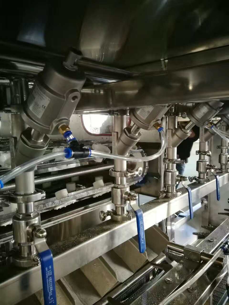
Modern large-container lines use wash-fill-seal integrated systems that minimize the time between final rinse and sealed product. This architecture reduces exposure to ambient air and potential secondary contamination in the filling environment.
Filling accuracy in these systems typically targets ±2 mL deviation, with capping pass rates above 99.6%. The capping system includes automatic cap sorting, cap disinfection (often via UV or ozone), and controlled pressing force to ensure seal integrity without crushing the barrel neck.
PLC-based control systems synchronize all stations, allowing single-operator oversight through a centralized HMI interface. Production data — including fill volumes, cap torque, and station temperatures — can be logged for traceability and regulatory compliance.
Stage 4: Post-Filling Inspection and Packaging
After sealing, barrels pass through visual inspection stations (light inspection boxes) where operators or vision systems check for fill level accuracy, cap alignment, and particulate contamination. Downstream packaging typically includes:
- Shrink sleeve labeling or adhesive labeling
- Inkjet or laser date coding
- Automatic bagging with food-grade PE or PP film
- Conveying systems that route finished barrels to palletizing or direct loading
The bagging stage protects the cap and neck from dust and handling contamination during storage and distribution — a practical necessity for barrels that may sit in delivery vehicles or customer premises for days before use.
Core Equipment and Selection Variables
When specifying a large-container line, procurement teams should evaluate these parameters against their actual operating conditions:
| Selection Variable | What to Assess |
|---|---|
| Barrel compatibility | 18.9L standard PC barrel, plus 10L, 15L, 20L, 22L variants; round or square; with/without handle; standard or wide-mouth |
| Rated capacity | 200–1,800 barrels/hour (configurable with 4–12 filling heads); verify against actual shift patterns and demand cycles |
| Washing stations | Number of stages, solution types, contact time, temperature control — matched to barrel return condition |
| Disinfection method | Ozone, UV (254 nm), chemical sanitizer, or combination; validated for target microbial reduction |
| Automation level | From semi-automatic single-station setups to fully integrated wash-fill-seal-palletize lines |
| Cleanroom requirements | ISO Class 8 (100,000) filling environment minimum; upgradeable to Class 7 (10,000) for stricter applications |
| Facility constraints | Floor space, ceiling height, utility connections (water, drainage, power, compressed air), and clean zone partitioning |
Water Treatment Integration
The filling line is only as reliable as the water treatment system feeding it. For purified water applications, a typical configuration includes multi-media filtration, activated carbon filtration, softening, precision filtration, and dual-stage reverse osmosis — followed by ozone and UV sterilization before the product water enters the sterile storage tank.
For spring water or mineral water, the treatment approach differs: the goal is to remove pathogens and particulates while preserving characteristic mineral content. Ultrafiltration replaces RO in many of these applications, with careful attention to source water variability across seasons.
Operational Boundaries and Common Risks
What These Lines Cannot Solve
A large-container production line is a manufacturing system, not a water quality guarantee. If the source water has contamination profiles that exceed the treatment system's design capacity — such as elevated heavy metals, persistent organic pollutants, or extreme turbidity spikes — the line will produce non-compliant product regardless of filling precision.
Similarly, barrel hygiene depends on the return loop. If customers store barrels in contaminated environments (garages, construction sites, agricultural settings), the incoming contamination load may exceed the washing system's design parameters. Operations teams must establish barrel rejection criteria and communicate storage guidelines to distribution partners.
Maintenance Realities
- Brush wear: Internal and external brushes degrade with use; replacement intervals depend on barrel volume and abrasion levels
- Nozzle clogging: Washing nozzles accumulate scale and debris; regular inspection prevents uneven coverage
- Sensor drift: Level sensors, temperature probes, and pressure transmitters require periodic calibration
- Seal degradation: Filling valve seals and capping head components wear with cycle count
- Chemical consumption: Washing solutions deplete and must be monitored for concentration and contamination
Maintenance should be driven by operational data — pressure differentials, flow rates, conductivity readings, and visual inspection results — rather than fixed calendar schedules.
Before, During, and After Adoption
Before: Site Assessment and Process Design
Successful implementation starts with water source testing, capacity calculations based on realistic demand projections (not peak theoretical output), and facility surveys that account for utility availability and cleanroom partitioning. Budget assessments should include not just equipment cost, but installation, validation, operator training, and first-year consumables.
During: Installation and Commissioning
Equipment fabrication and factory testing precede on-site installation. Commissioning follows a staged approach: single-unit testing, integrated line trials, acceptance runs with actual barrels and product water, and operator training on normal operation plus fault response. Documentation handover includes material certifications, SOPs, process flow diagrams, and maintenance schedules.
After: Sustained Operation and Support
Long-term line stability depends on disciplined operation, timely consumable replacement (filters, UV lamps, ozone generator components, seals), and responsive technical support when faults occur. Chuxin Mingwei provides after-sales maintenance support for installed systems, with service scope and response terms defined during project contracting.
Next Steps for Evaluation
If you are assessing a large-container water production line for a new facility, capacity expansion, or legacy line replacement, the following information will enable a meaningful technical discussion:
- Source water analysis report — including TDS, hardness, turbidity, microbial counts, and any known contaminants
- Target product specification — purified water, spring water, or mineral water; applicable regulatory standards
- Barrel format and condition — new or returnable; PC or PET; standard or non-standard sizes
- Capacity requirement — barrels per hour or per shift, accounting for demand variability
- Facility layout — available floor space, ceiling height, utility connections, and cleanroom zoning preferences
Share these details to receive a tailored process design and equipment proposal matched to your actual operating context.