
Matching Mixing Tank Capacity (1–20 TPH) with Filling Line Output: Process Integration & Selection Criteria
Matching Mixing Tank Capacity (1–20 TPH) with Filling Line Output
In water treatment and filling projects, a common engineering error is assuming that a water purification system rated at "X tons per hour" can directly feed a filling line running at the same speed. In reality, matching mixing tank capacity (1–20 TPH) with filling line output requires a detailed analysis of process continuity, buffer storage, and peak demand fluctuations.
For procurement managers and operations leads in the beverage, food, and pharmaceutical sectors, understanding this balance is critical to preventing production stoppages, ensuring consistent water quality, and optimizing capital expenditure.
Why Direct Capacity Matching Fails
A water treatment system (e.g., Reverse Osmosis or Ultrafiltration) produces water at a relatively constant rate. However, filling lines operate in cycles: they may stop for bottle changes, label jams, or shift breaks. If the filling line draws water directly from the treatment unit without adequate buffering, two risks emerge:
- Supply Shortages: During peak filling speeds, the treatment unit cannot replenish the line fast enough, causing the filler to run dry.
- Quality Instability: Frequent start-stop cycles in the treatment plant can compromise membrane performance and water consistency.
As noted in industry best practices for bottled water lines, single-machine high speed does not equal whole-line high capacity. The slowest link in the chain—often the water supply or the buffer tank turnover—dictates the true throughput.
Key Selection Criteria for Tank and Line Integration
When sizing your system for capacities between 1 and 20 TPH, consider these three technical dimensions:
1. Calculate Effective Buffer Volume
The mixing or buffer tank acts as the heart of the system, decoupling the continuous production of purified water from the intermittent consumption of the filler.
- Rule of Thumb:*
- The buffer tank should typically hold 30 to 60 minutes of the filling line's maximum consumption.
- Example:*
- For a line filling 18.9L barrels at 1,000 bottles/hour (approx. 19 TPH), a single 10-ton tank is insufficient if the water treatment unit is also rated at exactly 19 TPH. You need a treatment unit capable of exceeding the average draw plus a tank large enough to cover peak surges or treatment maintenance windows.
- Application Context:*
- For barrelled water filling lines handling 15L–22L PC/ABS containers, the surge demand during the initial rinse and final fill phases is significant. A modular architecture allows scaling capacity without full-line rework, but the buffer must be sized first.
2. Account for Water Loss and Non-Product Usage
The rated output of a filling machine refers to finished goods. The water treatment system must produce significantly more to account for:
- Rinsing and CIP:*
- Bottle washers and Clean-in-Place (CIP) systems consume large volumes of purified water. For instance, a fully automatic bottled purified water filling line integrates bottle washing, which requires high-pressure rinsing water that is discarded.
- System Recovery Rates:*
- Reverse Osmosis (RO) systems typically have a recovery rate of 50–75%. To get 10 TPH of product water, you may need to feed 15–20 TPH of raw water.
- Evaporation and Spillage:*
- Minor losses occur during transfer and filling accuracy adjustments (e.g., maintaining filling accuracy ≤ ±2 mL often involves slight overfills that are recycled or discarded).
3. Match Process Dynamics to Product Type
Different products impose different constraints on the mixing tank and filling interface:
- Mineral/Spring Water:*
- If using a Dual-membrane NF + UF process to balance purification with mineral retention, the flow rate may be lower than standard RO. The buffer tank must be larger to compensate for the slower production speed while maintaining high filling line speeds.
- Purified Water:*
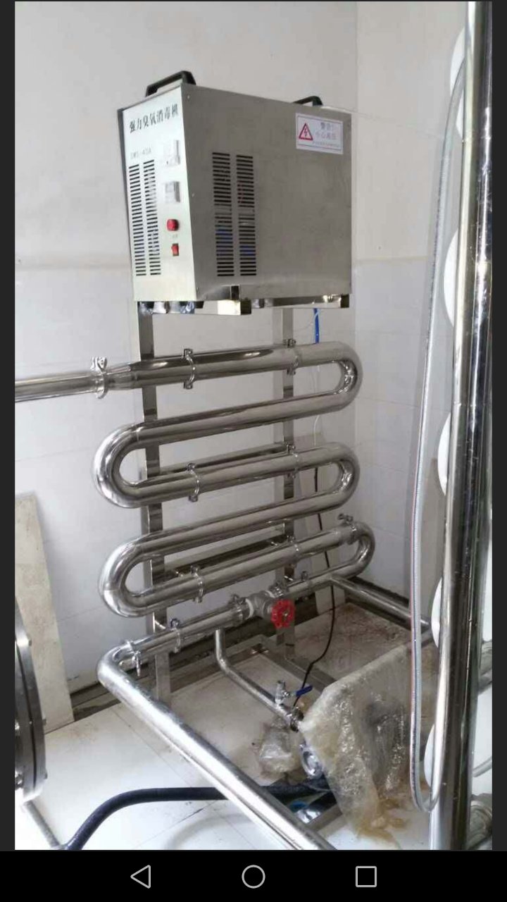
- Systems using two-stage RO deep purification combined with ozone and UV sterilization require sufficient residence time in the tank for disinfection contact. Rushing water from treatment to filler without adequate dwell time can compromise microbial standards.
Implementation Boundaries and Risks
Utility Constraints
Even if the tank and filler are perfectly matched, facility utilities can become the bottleneck.
- Power Supply:*
- High-capacity pumps (10–20 TPH) require stable, high-voltage power. Sudden starts can trip breakers if soft starters or VFDs are not specified.
- Drainage:*
- The wastewater generated during tank cleaning and RO rejection must be handled. A 20 TPH system can generate 10+ TPH of concentrate water that needs proper drainage infrastructure.
Space and Layout
Large buffer tanks (e.g., 20-ton stainless steel vessels) require significant floor space and headroom. In facilities with height restrictions, horizontal tanks or multiple smaller vertical tanks in series may be necessary. This impacts the workshop layout and piping design, which are critical steps in our Solution Design phase.
Automation and Control
Modern lines rely on PLC-based intelligent control systems to manage the handshake between the tank level and the filler speed.
- Low-Level Protection:*
- The filler must automatically slow down or stop if the buffer tank level drops below a set point.
- High-Level Cutoff:*
- The water treatment plant must shut off when the tank is full to prevent overflow and wasted energy.
- Integration:*
- For clean air purification systems operating in the same cleanroom, positive pressure requirements must be maintained even when water systems are cycling, requiring coordinated control logic.
Practical Steps for Procurement
- Define Peak Demand: Calculate the maximum liters/hour required by the filler, including rinse cycles and CIP.
- Determine Treatment Recovery: Ask suppliers for the specific recovery rate of the proposed RO/NF system based on your raw water report.
- Size the Buffer: Select a tank volume that provides at least 45 minutes of autonomy at peak speed.
- Verify Interfaces: Ensure the pump curves match the piping diameter and elevation differences between the tank and the filler.
- Review Maintenance Access: Confirm that the tank design allows for internal inspection and cleaning, crucial for long-term maintainability.
Conclusion
Successfully matching mixing tank capacity with filling line output is not just about arithmetic; it is about engineering resilience. A well-designed buffer system protects your investment by smoothing out operational variances, ensuring water quality stability, and maximizing the uptime of your bottled or barrelled water filling production line.
At Chuxin Mingwei, we engineer these systems based on your actual source water quality, target capacity, and facility constraints. We do not offer generic "one-size-fits-all" packages; instead, we provide tailored solutions that prioritize stability and long-term operability.
Next Steps
Ready to optimize your production line configuration? Share your target capacity (TPH), bottle/barrel size, and raw water source details. Our engineering team will provide a preliminary process flow diagram and equipment sizing recommendation tailored to your project needs.
Request a Solution Consultation