
PET Bottle Filling Line Maintenance & Repair Guide: Daily Checks, Service Intervals & Wear-Part Management
Who This Guide Is For
This guide is written for operations leads, maintenance engineers, and plant managers running PET bottled water filling lines — typically covering bottle sizes from 330 mL to 10 L, with integrated rinsing, filling, and capping functions. If your line was supplied as a turnkey system or retrofitted from an existing layout, the maintenance logic below applies to the core mechanical, pneumatic, and control subsystems that determine daily uptime and long-term filling accuracy.
The focus is on actionable checks, realistic service intervals, and wear-part management — not generic advice. Where specific thresholds depend on your water source, bottle format, or production volume, the guide flags those variables so you can confirm them with your equipment supplier or internal engineering team.
---
Step 1: Daily Pre-Shift Inspections (10–15 Minutes)
Before starting production, operators should complete a short checklist targeting the subsystems most likely to cause unplanned stops.
Rinsing Section
- Nozzle spray pattern: Verify that all rinsing nozzles produce a consistent, symmetrical spray. Uneven spray often indicates partial blockage from mineral deposits or biofilm — common when source water has high hardness or when CIP intervals have been extended.
- Clamp grip pressure: Check that bottle-neck clamps hold bottles firmly without deformation. Worn clamp pads cause misalignment as bottles transfer to the filling section.
Filling Section
- Fill valve sealing: Run a short test cycle and inspect for drip or overfill on the first 10–20 bottles. Dripping valves usually point to worn O-rings or seat seals — these are high-frequency wear parts in any volumetric or gravity filling system.
- Product tank level sensor: Confirm that the liquid-level probe responds correctly. A stuck probe can cause overflow or dry-run conditions, both of which damage downstream capping torque consistency.
Capping Section
- Cap sorter and chute: Ensure caps flow without jamming. Misaligned caps or deformed cap skirts are a leading cause of capping pass-rate drops below acceptable thresholds.
- Capping head torque: Use a torque gauge on a sample of 5–10 bottles. Deviation beyond your target range typically signals worn friction pads or spring fatigue in the capping heads.
---
Step 2: Weekly Service Intervals
Weekly maintenance addresses subsystems that degrade gradually and are not visible during daily checks.
Pneumatic System
- Air filter and regulator: Drain condensate from air-line filters. Moisture in pneumatic lines accelerates cylinder seal wear and causes inconsistent clamp or valve actuation.
- Cylinder stroke verification: Manually cycle key pneumatic cylinders (bottle-star-wheel clamps, cap-dispensing gates) and check for sluggish return strokes. Slow retraction often means internal seal wear or insufficient lubrication.
Conveyor and Star-Wheel Drives
- Chain tension and wear: Measure chain elongation on bottle-conveyor and star-wheel drives. Chains that have stretched beyond 2–3% of original pitch should be scheduled for replacement — running worn chains damages sprockets and increases motor load.
- Guide-rail alignment: Inspect bottle-guide rails for wear grooves. Misaligned rails cause bottle tipping at high speeds, especially with lightweight PET bottles in the 330 mL–500 mL range.
Electrical and Control
- Sensor cleanliness: Wipe photoelectric sensors (bottle-detection, cap-presence, liquid-level) with a lint-free cloth. Dust and water mist are the most common causes of false sensor triggers in humid filling environments.
- PLC alarm log review: Download and review the past week's alarm history. Recurring alarms — even if auto-reset — indicate developing faults that will eventually cause a hard stop.
---
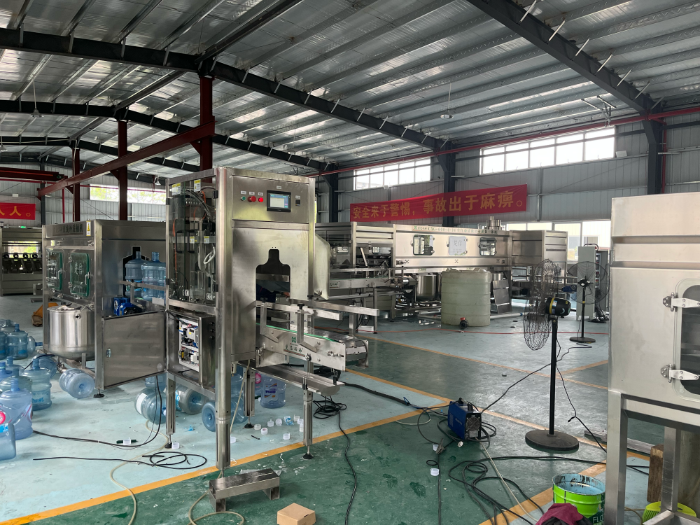
Step 3: Monthly and Quarterly Wear-Part Management
Wear-part replacement should be condition-based, not calendar-based. The following framework helps you decide when to replace rather than follow arbitrary schedules.
High-Frequency Wear Parts
| Component | Typical Wear Indicator | Replacement Trigger |
|---|---|---|
| Fill-valve O-rings and seat seals | Drip, overfill, or inconsistent fill volume | Visible flattening, cracking, or fill-volume deviation > ±2 mL |
| Capping-head friction pads | Capping torque drift or cap-skirt damage | Pad surface glazing or thickness loss > 1 mm |
| Rinsing-nozzle tips | Uneven spray or reduced flow | Mineral buildup that cannot be cleared by acid wash |
| Clamp pads (rinsing and filling star wheels) | Bottle slip or neck deformation | Visible groove wear or hardness loss |
| Conveyor chain and sprockets | Noise, vibration, or chain elongation | Elongation > 3% or sprocket tooth-hook wear |
Condition-Based Logic
Do not replace all consumables on a fixed calendar cycle. Instead, record operating data — fill volumes, capping torque values, rinsing pressure, and alarm frequency — and use trends to schedule parts. This approach reduces unnecessary downtime and spare-parts spend while preventing unexpected failures.
For water treatment consumables upstream of the filling line (RO membranes, UF cartridges, activated carbon, precision filter elements), replacement should be based on differential pressure, flow rate, conductivity, and cleaning history — not a fixed time interval. A well-maintained pretreatment system directly extends the service life of filling valves by reducing particulate and microbial load in the product water.
---
Step 4: Troubleshooting Common Faults
Fault: Fill Volume Inconsistency
- Check first: Product-tank liquid level stability, fill-valve O-ring condition, and bottle-neck dimensional tolerance.
- Secondary causes: Inconsistent bottle supply pressure (if using pressure-assisted filling), or PLC analog-output drift to the flow-control valve.
- Boundary note: If your line handles multiple bottle sizes (e.g., 500 mL and 5 L), verify that the recipe parameters in the HMI match the physical changeover settings. Mismatched recipes are a frequent root cause after format changes.
Fault: Cap Misalignment or Low Capping Pass Rate
- Check first: Cap-sorter orientation, chute alignment, and capping-head spring pressure.
- Secondary causes: Deformed cap skirts from upstream storage, or bottle-mouth ovality from the blow-molding stage. If bottle-mouth deformation is the root cause, the issue originates in the blow-molding system — specifically preform heating curves, stretch ratios, or mold cooling — and will not be resolved by adjusting the capping section alone.
Fault: Bottle Tipping on Conveyor
- Check first: Guide-rail width relative to bottle diameter, conveyor speed synchronization with star-wheel pitch, and bottle base flatness.
- Secondary causes: Lightweight PET bottles (common in 330 mL–500 mL formats) are more susceptible to tipping when conveyor transitions are not level or when air-blow dryers create lateral force.
---
Step 5: Cleanroom and Environmental Considerations
The filling environment directly affects maintenance frequency. In bottled water production, the filling zone typically requires controlled air quality — often designed to ISO Class 8 (100,000) standards, with options to upgrade to Class 7 (10,000) depending on product category and local regulatory requirements.
- HEPA filter integrity: Schedule annual DOP or PAO integrity tests on terminal HEPA filters. A compromised filter increases particulate load on filling valves and accelerates seal wear.
- Positive pressure differential: Verify that the filling room maintains positive pressure relative to adjacent packaging and warehouse zones. Loss of pressure differential allows unfiltered air ingress, increasing contamination risk and shortening CIP effectiveness.
- Temperature and humidity: High humidity accelerates corrosion on stainless-steel surfaces and electrical contacts. If your facility is in a coastal or tropical region, inspect stainless-steel weld seams and electrical enclosures quarterly for early signs of pitting.
---
Boundaries and Limitations
This guide provides a general maintenance framework for PET bottle filling lines used in drinking water production. Specific service intervals, torque values, and spare-part part numbers vary by equipment model, production speed, and water chemistry. Always cross-reference with the operation manual supplied with your line.
Maintenance decisions should also account for local food-safety regulations, SC licensing requirements, and any third-party audit standards your facility must meet. When in doubt, request a maintenance audit or remote diagnostic session from your equipment supplier before scheduling major overhauls.
---
Next Steps
If your team is experiencing recurring faults, rising wear-part consumption, or fill-accuracy drift that daily checks cannot resolve, the next step is a structured line assessment. Share your current bottle formats, hourly capacity, water source conditions, and recent alarm logs — a qualified water treatment equipment manufacturer can map these to specific subsystem adjustments, spare-parts kits, or control-system updates.
For new projects or line expansions, early involvement of your equipment supplier in facility layout, cleanroom zoning, and utility planning reduces long-term maintenance burden and improves overall line stability.