
Pulp-Containing Beverage Filler Valve Clogging Prevention: Diagnostic Steps and Equipment Boundaries
Who This Guide Is For
This article addresses operations leads, maintenance engineers, and procurement managers running or specifying hot-fill or ambient-fill production lines for juice, tea beverages, fruit drinks, or sports drinks that contain pulp, fruit cells, or suspended solids. If your line fills clear liquids such as purified water or carbonated soda, the failure modes and valve requirements differ substantially and are outside the scope of this guide.
The Direct Answer: What Causes Filler Valve Clogging on Pulp Lines
Filler valve clogging on pulp-containing beverage lines almost never stems from a single root cause. In practice, blockages result from three conditions converging simultaneously: pulp particle dimensions exceeding the valve's internal flow geometry, insufficient or poorly routed CIP (Clean-In-Place) flushing at the valve seat, and product residue accumulating during changeovers or extended production runs. Addressing only one factor — for example, installing a larger-bore valve — without correcting the other two typically shifts the problem downstream rather than eliminating it.
Root Causes Ranked by Field Frequency
1. Pulp Particle Size Exceeds Valve Flow Path Clearance
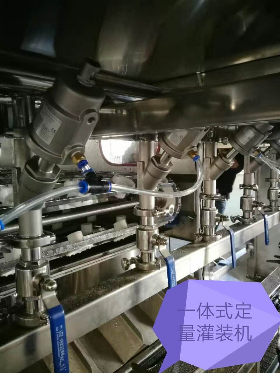
Standard gravity or low-vacuum filler valves are engineered for clear or lightly viscous liquids. When pulp particles, citrus cells, or fiber strands enter the valve chamber, they lodge at the valve seat, the sealing ring groove, or the return-flow channel — causing partial or complete blockage.
Field checks:
- Measure the maximum particle dimension in your finished beverage, not just the average. A single 3 mm fiber can jam a valve rated for 2 mm clearance.
- Confirm whether upstream filtration or pulping equipment has a defined mesh or screen size. A damaged or bypassed screen allows oversized particles to reach the filler bowl undetected.
- Verify that the filler valve's internal flow diameter and seat geometry are explicitly rated for particulate-containing products. Standard water-filling valves — such as those used on PET bottled purified water lines — are not interchangeable with pulp-rated valves. Water, hot-fill products, and carbonated beverages have fundamentally different requirements for filler valve type, temperature tolerance, pressure dynamics, and hygiene control.
2. Inadequate CIP Coverage at the Valve Seat
On hot-fill juice and tea beverage lines, filling temperatures (typically 85–92 °C) keep product viscosity low during production. However, when the line stops — for a changeover, scheduled break, or fault — residual product cools inside the valve body. Pulp and sugar residues then gel or caramelize on the valve seat and sealing surfaces, progressively restricting flow.
Field checks:
- Does your CIP circuit include a dedicated flush path through each individual filler valve, or does it only rinse the filler bowl and external surfaces?
- Is the CIP flow velocity at the valve seat sufficient to dislodge settled pulp? Low-flow CIP may clean the piping while leaving the valve chamber untouched.
- Are CIP cycles triggered automatically after every stoppage exceeding a defined duration, or do they rely on manual operator initiation? Manual CIP scheduling is a frequent gap on lines running multiple SKUs.
Key quality control points on hot-fill juice lines — including filling temperature, sterilization and holding conditions, CIP coverage, fill level accuracy, bottle mouth hygiene, cooling curves, and changeover cleaning — all directly influence valve clogging risk and must be verified together rather than in isolation.
3. Product Residue Accumulation During Changeovers
Beverage lines that switch between pulp-containing and clear products (e.g., from orange juice with pulp to clear apple juice) face a specific risk: pulp residue trapped in the valve is carried into the next product batch, causing both clogging and cross-contamination.
Field checks:
- Is there a validated changeover cleaning procedure that includes valve disassembly or extended CIP, not just a standard bowl rinse?
- Do you track the time between the last pulp-product fill and the first clear-product fill? Compressed changeover windows are a common pressure point where cleaning steps get shortened or skipped.
4. Filler Bowl Sedimentation During Low-Speed Runs
Even when individual valves are correctly specified, pulp can settle in the filler bowl during low-speed runs or temporary stops. This concentrated sediment is then pushed into the valves as a slug when the line restarts at full speed.
Field checks:
- Does the filler bowl have an agitator or recirculation loop to keep pulp in suspension?
- Is the bowl level control stable? Rapid level swings can disturb settled pulp and send concentrated slugs into the valve array.
Field Diagnostic Checklist
Use this sequence when clogging is reported on the production floor. Work top-down to avoid misdiagnosis.
| Step | Check Point | What to Look For |
|---|---|---|
| 1 | Upstream screen or pulper | Screen integrity, mesh size, bypass leaks |
| 2 | Filler bowl interior | Sediment layer, agitator function, level stability |
| 3 | Valve flow path (disassembled) | Pulp trapped at seat, seal groove, or return channel |
| 4 | CIP circuit verification | Flow path through valve, velocity, temperature, duration |
| 5 | Changeover log review | Cleaning steps taken, time elapsed, product sequence |
| 6 | Fill weight and level data | Pattern of under-fills — random (particle jam) vs. progressive (buildup) |
Key diagnostic distinction: If under-fills appear randomly across different valves and bottles, the cause is likely particle ingress from upstream (Steps 1–2). If under-fills worsen progressively over a shift and improve after CIP, the cause is residue buildup inside the valve (Steps 4–5).
Corrective Actions and Equipment Considerations
Valve Selection for Pulp-Containing Products
Pulp-containing beverages require filler valves with wider flow channels, simplified internal geometry, and self-cleaning or flush-through designs. Negative-pressure (vacuum) fillers and gravity fillers with large-bore poppet valves are common choices for these applications. All product-contact surfaces must be compatible with hot-fill temperatures and acidic fruit formulations — typically 304 or 316L stainless steel.
Pulp-containing, dairy, or high-viscosity products require separate process confirmation and cannot be automatically assigned to a standard hot-fill line. The filler valve, bowl design, CIP routing, and bottle handling system must all be matched to the actual product characteristics.
Equipment boundary: A filler valve rated for pulp does not automatically mean the entire filling machine is suitable. The bottle conveying system (e.g., neck-hanging vs. base-riding), the capping head configuration, and the downstream inversion or holding tunnel must also be matched to the product and bottle format. On hot-fill juice lines, the integrated washing-filling-capping structure, bottle neck conveying method, and negative-pressure filling approach must all be confirmed against the actual product recipe and packaging format before procurement.
CIP System Modifications
If CIP coverage is the identified gap, corrective actions include:
- Adding individual valve flush nozzles or a CIP manifold that routes cleaning solution through each valve's internal flow path.
- Increasing CIP flow velocity and temperature at the valve seat — verified with a flow meter and temperature probe at the furthest valve, not just at the CIP supply outlet.
- Automating CIP triggers so that any line stoppage beyond a defined threshold (e.g., 5 minutes) initiates a valve flush cycle without operator intervention.
Process and Operational Controls
- Define a maximum pulp particle specification in your product quality standard and verify it at the pulper outlet, not only at the finished-goods laboratory.
- Establish a minimum agitator speed for the filler bowl during any run below rated capacity.
- Document and enforce a changeover cleaning SOP that includes valve-level verification, not just visual bowl inspection.
Boundaries and Limitations
- This guide addresses mechanical and process-related clogging of filler valves. Microbiological contamination, valve seal degradation, or pneumatic actuator faults present different symptoms and require separate diagnostic procedures.
- The particle size thresholds, CIP parameters, and valve types discussed here represent general engineering guidance. Your specific product formulation, bottle format, and regulatory requirements will determine the final equipment specification.
- Equipment originally designed for clear water filling — such as standard bottled purified water or mineral water production lines — cannot be retrofitted for pulp products by changing the valve alone. The filler bowl, product piping, CIP system, and often the bottle handling system all require review and potential modification.
Next Steps for Your Line
If your production line is experiencing recurring valve clogging and the field checks above point to a valve or CIP design gap, the recommended next step is a product-specific line review. This assessment should be based on:
- Your current product recipe, including pulp type, particle size range, and filling temperature.
- Your existing filler valve model, flow path drawings, and CIP circuit layout.
- Your target capacity (bottles per hour) and bottle format range.
With these inputs, a tailored assessment can identify whether the solution is a valve upgrade, a CIP circuit modification, or a broader line reconfiguration — and what the implementation timeline and production impact would be.