
Turnkey Water Plant Project Process Flow: Engineering Stages, Equipment Logic & Implementation Boundaries
Who This Process Flow Applies To
Procurement managers, plant engineers, and operations leads evaluating a new bottled or barrelled water production facility—or expanding an existing one—need more than a list of machines. A turnkey water plant project process flow defines how raw water characteristics, target water quality, packaging format, and site constraints translate into a working production line. This article maps the engineering stages, decision points, and boundaries that shape real-world water plant delivery for beverage, food, pharmaceutical, and industrial clients.
Stage 1: Raw Water Assessment and Target Quality Definition
Every turnkey water plant begins with a raw water quality report. Source water—whether municipal supply, groundwater, mountain spring, or surface water—carries distinct profiles of suspended solids, residual chlorine, hardness, iron and manganese, total dissolved solids (TDS), conductivity, and microbial load. These parameters determine the pretreatment chain, membrane selection, and disinfection strategy.
Key decision checkpoint: The target product water standard must be locked before equipment configuration. Purified water for bottling requires a different process chain (typically dual-stage reverse osmosis with ozone and UV sterilization) than spring water, where mineral retention is a priority and nanofiltration or ultrafiltration may be more appropriate. Industrial high-purity water applications may add electrodeionization (EDI) downstream of RO.
Boundary note: A flow rate specification alone (e.g., "5 tons per hour") is insufficient for system design. The same nominal capacity can require entirely different pretreatment configurations, membrane arrangements, recovery rates, and cleaning protocols depending on the raw water source and the end-use standard.
Stage 2: Water Treatment System Design and Configuration
Once raw water data and target quality are confirmed, the treatment train is engineered. A typical configuration chain includes:
- Pretreatment: Multi-media filtration, activated carbon adsorption, water softening (sodium ion exchange for hardness control), and precision filtration to protect downstream membranes.
- Membrane separation: Reverse osmosis (RO) for deep desalination, ultrafiltration (UF) for particulate and microbial removal, or nanofiltration (NF) for selective mineral retention.
- Post-treatment and disinfection: Ozone generation and mixing, ultraviolet sterilization (254 nm), and finished water storage with recirculation loops.
- Monitoring and CIP: Online water quality instruments, constant-pressure supply pumps, and clean-in-place systems for pipeline sanitation.
Configuration logic: Softening systems reduce calcium and magnesium hardness to prevent membrane scaling, but softened water still contains dissolved salts and cannot substitute for RO permeate. Whether softening is placed before RO depends on the raw water hardness and the membrane manufacturer's fouling thresholds. Dual-tank softener configurations are common where continuous supply is required, with one tank in service while the other regenerates.
Boundary note: Mineral water and spring water projects require careful balancing of purification and mineral retention. The choice between UF, NF, and RO is driven by the target mineral profile, local drinking water standards, and the disinfection method—not by equipment naming conventions.
Stage 3: Filling Line Engineering and Integration
The filling line is configured around the packaging format, production capacity, and hygiene requirements established in earlier stages.
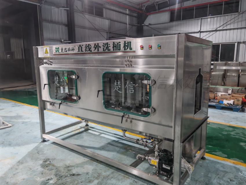
Bottled Water Filling Lines
For PET bottle formats (500 mL to 18.9 L), the core workflow integrates bottle washing, precision filling, and capping in a single enclosed unit. Key parameters include:
- Bottle compatibility: Diameter range (approximately 50–100 mm), height range (150–330 mm), and cap type (plastic screw cap, sports cap, or aluminum cap).
- Filling accuracy: Typically ≤ ±2 mL for volumetric or level-fill systems.
- Capping pass rate: ≥99.6% with torque control and cap-presence detection.
- Hygiene controls: Rinse water quality and pressure, bottle-mouth secondary contamination prevention, no-bottle-no-fill logic, and dead-zone-free cleaning design.
Upstream connections link to the water treatment system and bottle blowing or unscrambling equipment. Downstream operations include light inspection, inkjet coding, labeling, and end-of-line packaging.
Barrelled Water Filling Lines
For 3-gallon and 5-gallon returnable barrels, the process chain is longer due to barrel recovery and reconditioning:
Empty barrel return → Inspection and sorting → Cap removal → External brushing → Internal brushing → Multi-station washing and disinfection → Finished water rinse → Filling → Cap application and pressing → Light inspection → Labeling/shrink sleeving → Coding → Bagging → Conveyor to warehouse
Equipment selection depends on barrel type and mouth specification, the cleanliness condition of returned barrels, hourly output targets, the number of wash stations, disinfection method, and the degree of automation required for cap handling, inspection, and palletizing.
Stage 4: Clean Air and Facility Environment Design
Water bottling and barrelled filling operations require controlled air environments to protect product integrity at the filling zone. Clean air purification systems are engineered to meet ISO 14644-1 Class 8 (100,000) standards, with optional upgrades to Class 7 (10,000) for higher-sensitivity applications.
Design parameters include:
- Filtration: H13 HEPA filters at terminal supply points.
- Airflow range: 1,500–20,000 m³/h, selected based on room volume, occupancy, and process heat load.
- Pressure zoning: Positive pressure in filling cleanrooms relative to adjacent unclassified areas, with dedicated duct routing and return air paths.
- Control: PLC and HMI interfaces with real-time diagnostics and remote-ready monitoring capability.
Boundary note: Clean air system scope must be defined alongside the filling line layout. Airflow patterns, duct routing, and pressure differentials are site-specific and cannot be standardized across different facility footprints.
Stage 5: Installation, Commissioning, and Operator Training
The physical delivery phase follows a structured sequence:
- Equipment fabrication and factory acceptance testing (FAT): Assembled units are tested against design specifications before shipment.
- Site preparation: Utility connections (power, water supply, drainage, compressed air, and cooling water), floor leveling, and cleanroom partition completion.
- Installation and mechanical completion: Equipment positioning, pipeline welding, electrical termination, and instrumentation calibration.
- Commissioning and site acceptance testing (SAT): Water is introduced, process parameters are tuned, filling accuracy and capping torque are verified, and CIP cycles are validated.
- Operator training: Plant staff receive instruction on normal operation, changeover procedures, routine maintenance, and fault response.
Checkpoint: Commissioning must validate the complete chain—from raw water intake through treatment, storage, filling, and packaging—not isolated subsystems. A filling machine that performs correctly on test water may behave differently when connected to the actual treatment system under production flow rates.
Stage 6: Post-Installation Support and Operational Boundaries
After handover, sustained operational support defines long-term plant reliability. This includes:
- Preventive maintenance schedules for membrane cleaning, filter replacement, and mechanical wear parts.
- Consumable and spare parts supply aligned with the installed equipment configuration.
- Process optimization as raw water conditions shift seasonally or production targets change.
- Capacity expansion planning when market demand outpaces the original design throughput.
Boundary note: Turnkey delivery does not eliminate the buyer's responsibility for ongoing raw water monitoring, utility stability, and operator discipline. Equipment warranties and service agreements define the support scope; conditions outside those boundaries—such as unapproved chemical dosing or operation beyond rated capacity—fall outside standard coverage.
Common Implementation Risks and How to Mitigate Them
| Risk Area | Typical Cause | Mitigation Approach |
|---|---|---|
| Membrane fouling or premature failure | Inadequate pretreatment for actual raw water conditions | Base pretreatment design on a current, representative raw water analysis—not historical averages |
| Filling accuracy drift | Bottle dimension variation or worn filling valves | Specify bottle tolerance ranges in the equipment contract; include valve maintenance intervals |
| Microbial contamination post-filling | Insufficient clean air zoning or cap sterilization | Validate cleanroom pressure differentials and cap disinfection contact time during SAT |
| Capacity shortfall | Peak demand miscalculated or shift patterns not accounted for | Convert daily and seasonal demand into hourly throughput requirements before sizing |
| Utility interruption | Undersized power supply, water feed, or drainage | Confirm utility capacity with site surveys before equipment fabrication begins |
Next Steps for Procurement and Project Teams
If you are evaluating a turnkey water plant project, the most productive first step is to assemble three inputs: a current raw water quality report, a defined target product water standard, and a preliminary production capacity requirement (including shift patterns and seasonal peaks). These inputs allow an equipment manufacturer to propose a treatment train and filling line configuration that is specific to your site—not a generic catalog selection.
For a detailed discussion of how Chuxin Mingwei engineers water treatment systems and filling lines around your actual source water, facility layout, and production targets, contact our project team to initiate a technical consultation.