
Water Plant Cleanroom Process Flow: Design Logic, Zoning Rules & Equipment Integration
Decision Objective
For beverage, food, pharmaceutical, and industrial water projects, the cleanroom is not a standalone "add-on" — it is the environmental control layer that determines whether the water treatment and filling line can consistently meet microbiological and particulate targets. The objective of this memo is to help procurement managers, operations leads, and digital project teams understand the water plant cleanroom process flow as an engineered system, so they can evaluate proposals, challenge assumptions, and avoid costly retrofits after installation.
The core question is not "do we need a cleanroom?" but rather: what cleanliness class, zoning layout, and airflow logic are required for our specific water source, filling format, and production capacity?
Alternatives: Cleanroom Classes and Where They Apply
Cleanroom classification in water plants is typically referenced against ISO 14644-1. The two most common targets in this industry are:
- ISO Class 8 (100,000): The baseline for most bottled and barrelled drinking water filling zones, including purified water, spring water, and mineral water lines. This class is appropriate when the filling environment must control airborne particulates and microbial load around open bottle mouths, capping stations, and conveyor transfer points.
- ISO Class 7 (10,000): Required when the product is more sensitive (e.g., pharmaceutical-grade water, certain functional beverages, or aseptic cold-fill applications), or when local regulatory standards demand a tighter envelope around the filling and capping zone.
The choice between Class 8 and Class 7 is not a matter of "better is always better." A higher class demands more air changes per hour, higher static pressure differentials, stricter gowning protocols, and greater energy consumption. The correct class must be justified by the product risk profile and the filling method — not by generic industry preference.
Evidence: How the Cleanroom Process Flow Is Structured
1. Zoning Based on Contamination Risk
A water plant cleanroom is divided into zones of decreasing contamination risk, moving from the outside in:
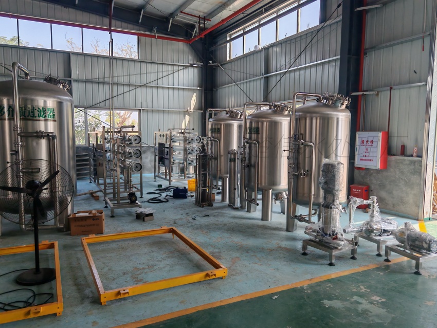
- General production area: Raw water intake, pretreatment (multi-media filtration, activated carbon, softening), and equipment rooms. No cleanroom classification required, but hygiene and drainage standards still apply.
- Controlled area: Post-RO or post-UF water storage, ozone/UV sterilization modules, and CIP systems. This area may operate under controlled access and basic particulate monitoring.
- Clean filling zone: The core cleanroom — encompassing the bottle/barrel washing, filling, and capping stations. This is where ISO Class 8 (or Class 7) compliance is enforced. The boundary between the controlled area and the clean filling zone is typically a physical partition with interlocked doors or air showers.
The zoning logic must align with the actual process chain. For example, in a barrelled water line, the standard workflow runs from empty barrel recovery through inspection, cap removal, external/internal brushing, multi-stage washing and disinfection, final rinsing, filling, capping, and inspection. The cleanroom envelope typically begins at the final rinse and extends through filling and capping — because this is where the sterilized barrel interior is exposed to the ambient environment.
2. Airflow and Pressure Zoning
The cleanroom process flow depends on directional airflow:
- Positive pressure is maintained in the clean filling zone relative to adjacent controlled and general areas. This prevents unfiltered air from migrating inward when doors open.
- Airflow patterns are designed to sweep particulates away from open product contact points. In most water filling cleanrooms, a downward or horizontal laminar flow is not required (unlike semiconductor fabs); instead, turbulent dilution ventilation with high-efficiency terminal filtration is the standard approach.
- HEPA filtration (H13 class) at the terminal supply point is the norm for ISO Class 8 water plant cleanrooms. Pre-filtration stages (G4, F8) protect the HEPA filters and extend their service life.
Airflow volume is project-specific. For a typical bottled or barrelled water filling room, the air change rate is calculated based on room volume, personnel count, equipment heat load, and the target particle count. Published ranges for water plant cleanrooms span from approximately 1,500 to 20,000 m³/h depending on room size and classification target.
3. Equipment Integration Within the Cleanroom
The cleanroom does not operate in isolation. Its process flow must be synchronized with the filling line:
- Bottle/barrel conveying: Conveyors that cross from non-classified to classified zones must pass through sealed wall penetrations with air curtains or strip curtains to minimize pressure loss.
- Filling machine enclosure: The washing-filling-capping monoblock is typically the largest heat and moisture source inside the cleanroom. Its exhaust and drainage must be routed without compromising room pressure.
- Cap handling: Cap sorting, sterilization, and delivery systems must be located within or immediately adjacent to the clean zone, because caps contact the bottle mouth directly.
- Personnel and material flow: Air showers for personnel and pass-through boxes for materials (preforms, caps, labels) are positioned at zone boundaries.
A critical integration point is the PLC + HMI control system. Modern cleanroom systems for water plants use centralized PLC control with real-time diagnostics for differential pressure, temperature, humidity, and filter status. The interface should be remote-ready, allowing the plant's operations team to monitor cleanroom parameters alongside filling line metrics (filling accuracy, capping torque, output rate) on a single dashboard.
Recommendation: A Practical Evaluation Checklist
When reviewing a cleanroom proposal for your water plant, verify the following:
| Evaluation Item | What to Confirm |
|---|---|
| Cleanroom class justification | Is ISO Class 8 or Class 7 selected based on your specific product, filling method, and regulatory requirements — not a default assumption? |
| Zoning map | Does the layout clearly show the boundary between general, controlled, and clean zones, aligned with your actual process chain (e.g., barrel washing → filling → capping)? |
| Airflow calculation | Has the supplier provided an airflow volume and air change rate calculation based on your room dimensions, equipment layout, and personnel count? |
| Pressure cascade | Is a positive pressure cascade documented from clean zone → controlled zone → general area, with target differential pressures at each boundary? |
| HEPA terminal filtration | Are H13 HEPA filters specified at the supply terminals, with accessible pre-filtration stages? |
| Equipment penetration sealing | Are conveyor wall penetrations, drainage routes, and cable entries designed to maintain room integrity? |
| Control system integration | Does the PLC + HMI system provide real-time monitoring of cleanroom parameters, and can it integrate with your filling line controls? |
| Upgrade path | If you start at ISO Class 8, is the ductwork, fan capacity, and structural envelope designed to support a future upgrade to Class 7 without full reconstruction? |
Boundaries and Risks
- Cleanroom class alone does not guarantee product safety. The water treatment process upstream (RO, UF, ozone, UV sterilization) and the hygiene of the filling equipment itself are equally critical. A Class 7 cleanroom cannot compensate for inadequate source water treatment or poor CIP protocols.
- Operational discipline matters more than design specifications. Gowning compliance, door interlock usage, filter replacement schedules, and differential pressure monitoring must be enforced daily. A cleanroom that is designed to Class 8 but operated without discipline will underperform a well-managed Class 8 room with simpler equipment.
- Energy cost is a long-term factor. Higher air change rates and tighter temperature/humidity control increase HVAC energy consumption. The cleanroom design should balance microbiological safety with realistic operating costs for your production schedule.
- Retrofitting is expensive. If the cleanroom envelope is not planned alongside the filling line layout from the beginning, adding or upgrading cleanroom zones later often requires structural modification, duct rerouting, and production downtime.
Next Steps
If you are evaluating a water plant project that includes a cleanroom requirement, the most productive starting point is to align three inputs: your source water quality report, your target product and filling format (bottle size, barrel type, cap style, output capacity), and your facility layout constraints (room dimensions, ceiling height, utility access). These three inputs determine the cleanroom class, zoning layout, and airflow configuration — and they must be resolved before equipment specifications are finalized.
Chuxin Mingwei engineers cleanroom systems as an integrated component of water treatment and filling line projects, with site-specific airflow design, HEPA filtration, PLC-based monitoring, and commissioning support. For a technical review of your cleanroom requirements, share your project parameters and our engineering team will provide a zoning and configuration assessment.
Explore related technical resources on water plant equipment installation and commissioning to understand how cleanroom integration fits into the broader delivery and startup workflow.