
Bottled Water Filling Equipment Working Principle: Core Components, Operational Logic & Application Scenarios
Decision Objective
Procurement managers and operations leads evaluating bottled water production lines need to understand not just what the equipment does, but how its core subsystems interact under real production conditions. The working principle of bottled water filling equipment determines line stability, hygiene control, and long-term maintainability—factors that directly affect output quality and total cost of ownership.
This memo explains the operational logic of integrated washing-filling-capping systems, maps key components to their functions, and clarifies the application boundaries that should guide your selection.
Core Working Principle: The Three-in-One Integration
Modern bottled water filling equipment operates on a continuous three-in-one principle: bottle washing, water filling, and capping are executed within a single enclosed unit. This integration is not merely a space-saving design choice—it fundamentally reduces the exposure time of open bottles and treated water to the ambient environment, lowering the risk of secondary contamination between the cleanroom and the sealed container.
Stage 1: Bottle Washing
Empty bottles are fed into the washing station via an air conveyor or starwheel system. Grippers clamp the bottle neck, invert the bottle 180 degrees, and rinse the interior with treated product water or sterile water under controlled pressure. The washing cycle removes particulate residue and reduces microbial load before the bottle enters the filling zone.
Key operational variable: Rinse water pressure and contact time must be calibrated to bottle volume. A 5 L bottle requires different rinse dynamics than an 18.9 L format.
Stage 2: Precision Filling
After washing, bottles are transferred to the filling station. The filling valve operates on a gravity or micro-pressure principle—product water flows from the sterile storage tank through the valve into the bottle until a preset liquid level is reached. The valve then closes, and the filled bottle moves to the capping station.
Chuxin Mingwei's filling systems achieve a filling accuracy of ≤ ±2 mL across compatible bottle sizes. This precision is maintained through PLC-controlled valve timing and level sensors that compensate for minor variations in bottle geometry.
Key operational variable: Filling speed must be balanced against valve drip risk and foam generation. Higher line speeds (e.g., 2,500 bottles/hour for purified water lines) require more sophisticated valve sequencing than lower-speed configurations.
Stage 3: Capping and Sealing
Caps are sorted, oriented, and disinfected (typically via UV or ozone treatment) before being applied to the filled bottle. A capping head screws or presses the cap onto the bottle neck with controlled torque. The capping pass rate on properly configured systems reaches ≥99.6%, with rejected bottles diverted to a separate lane for rework.
Key operational variable: Cap-to-bottle thread compatibility and torque settings must be validated for each packaging format. Mismatched caps are a leading cause of seal failure and product returns.
Control Logic: PLC-Based Coordination
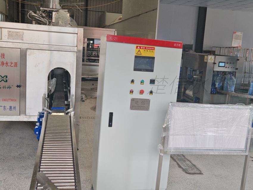
The entire washing-filling-capping sequence is governed by a PLC (Programmable Logic Controller) system with an HMI (Human-Machine Interface) panel. The PLC synchronizes motor speeds, valve timing, sensor feedback, and fault detection across all three stations.
Practical functions managed by the control system include:
- Bottle detection: Photoelectric sensors confirm bottle presence before each operation. No bottle—no wash, no fill, no cap. This prevents water waste and mechanical damage.
- Fault diagnostics: The HMI displays real-time alerts for jammed bottles, low cap supply, pressure deviations, or motor overload conditions.
- Speed adjustment: Operators can adjust line speed within the rated capacity range without stopping the line, allowing gradual ramp-up during shift changes.
- CIP integration: For lines requiring Clean-in-Place cycles, the PLC can initiate automated flushing sequences for product contact surfaces between production runs.
Application Boundaries: Where This Principle Applies
The three-in-one working principle is most effective within defined operational boundaries. Understanding these limits prevents over-specification or under-performance.
Compatible Formats
Integrated washing-filling-capping units handle bottle sizes from small single-serve formats up to 18.9 L (5-gallon) containers. However, switching between significantly different bottle diameters or neck finishes requires changeover parts (starwheels, guide rails, filling valve adapters) and adjustment time. Lines designed for 330 mL to 10 L multi-format switching must account for changeover duration in capacity planning.
Capacity Range
Rated output varies by configuration:
- Bottled spring water lines: 200–1,800 bottles/hour (based on 18.9 L format)
- Bottled purified water lines: 200–2,500 bottles/hour (customizable)
Actual throughput depends on upstream water treatment output, bottle supply continuity, and downstream packaging speed. A filling machine rated at 1,800 bottles/hour cannot sustain that rate if the RO system produces water at a lower flow rate or if the labeling station creates a bottleneck.
Cleanroom Requirements
The filling zone must operate within a controlled environment. For bottled water production, ISO Class 8 (100,000) cleanroom standards are typical, with optional upgrades to Class 7 (10,000) for higher-risk products. Airflow patterns, pressure zoning, and HEPA filtration in the filling room directly affect the contamination control that the three-in-one machine is designed to support.
Selection Variables for Procurement Teams
When specifying bottled water filling equipment, the following variables should drive your technical evaluation:
| Variable | What to Clarify |
|---|---|
| Bottle format range | Which sizes and neck finishes will you run? How often will you change over? |
| Source water quality | Does your raw water require single-stage RO, dual-stage RO, or NF+UF treatment before filling? |
| Target production capacity | What is your required bottles/hour at peak demand, and what is your realistic daily run time? |
| Automation level | Do you need fully automated cap sorting and disinfection, or is semi-automatic cap feeding acceptable? |
| Facility constraints | What are your floor space, ceiling height, utility connections, and cleanroom zoning limitations? |
| Upstream/downstream integration | Will the filling line connect to an existing water treatment system, blow molding unit, or end-of-line packaging equipment? |
Risk Boundaries and Common Misconceptions
Misconception 1: The filling machine alone determines product safety.
In reality, the filling machine is one link in a chain. Product water quality depends on the treatment system (RO, UF, ozone, UV). Container hygiene depends on bottle washing parameters and cap disinfection. Environmental hygiene depends on cleanroom design and operator protocols. The three-in-one machine reduces exposure risk, but it cannot compensate for failures upstream or in the surrounding environment.
Misconception 2: Higher rated speed is always better.
A line rated at 2,500 bottles/hour requires proportionally higher water treatment output, more robust bottle supply logistics, and faster downstream packaging. If your actual demand is 800 bottles/hour, a lower-speed configuration may offer better filling accuracy, lower energy consumption, and simpler maintenance.
Misconception 3: All bottles can run on the same machine without changeover.
Switching from 5 L to 18.9 L bottles involves mechanical adjustments and validation runs. Procurement teams should request documented changeover procedures and estimated time requirements from the equipment supplier before finalizing specifications.
Recommendation
For procurement teams evaluating bottled water filling equipment, the working principle should be assessed as a system-level question—not a standalone machine specification. The three-in-one washing-filling-capping integration provides genuine hygiene and efficiency advantages, but its effectiveness depends on correct matching to your water source characteristics, bottle formats, capacity requirements, and facility conditions.
Chuxin Mingwei engineers each filling line from actual source water quality reports, target water standards, production capacity targets, and facility layout constraints. This site-specific approach ensures that the equipment's working principle translates into stable, maintainable production—not just a rated capacity on a datasheet.
Next Steps
If you are preparing a bottled water production project, the most productive starting point is a technical consultation based on your specific inputs: source water analysis report, target bottle formats, required hourly output, and available facility layout. This allows the engineering team to map equipment capabilities to your actual operational context and define a clear scope for design, manufacturing, installation, and commissioning.
For detailed information on line deployment and support scope, review our resources on water plant equipment installation and commissioning to understand what is included in a typical project delivery.
Beyond the three-in-one monoblock, a complete bottled water production line integrates critical upstream and downstream subsystems that directly influence filling performance and final product safety. Upstream, the water treatment chain—comprising raw water tanks, multi-media and activated carbon filtration, softening, precision filtration, and single- or double-pass reverse osmosis—determines the baseline water quality entering the filler. Disinfection is typically achieved through ozone generators with mixing units or ultraviolet sterilizers, each with distinct operational constraints: ozone requires careful control of dosing, contact time, off-gas, and by-product risks, while UV effectiveness depends on water quality, flow rate, lamp degradation, and sleeve fouling, offering no residual protection. Downstream of the filler, the line incorporates cap sorting and pressing systems, cap disinfection equipment, light inspection boxes, liquid level and missing-cap detection, labeling or sleeve-shrinking machines, inkjet coders, and film or carton packaging stations. For barrelled water formats (3-gallon, 5-gallon, and 10 L–18.9 L recyclable or one-way barrels), the process chain expands significantly to include barrel recovery, inspection and sorting, de-capping, external and internal brushing, multi-stage washing and disinfection, final rinsing with product water, filling, capping, light inspection, sleeve labeling, shrink wrapping, coding, bagging, and palletizing—making barrel cleanliness, detergent residue control, final rinse water quality, and filling-room secondary contamination the core quality determinants rather than filling accuracy alone.