
How Electroplating Pure Water Systems Treat Rinse Water: Core Stages, Equipment Logic, and Operational Boundaries
Who This Article Is For
This article is written for procurement managers, operations leads, and digital project teams evaluating water treatment equipment for electroplating applications. If you are responsible for specifying or purchasing a pure water system that ensures consistent rinse quality, protects plating bath chemistry, and meets regulatory discharge limits, the technical details below will help you ask the right questions and compare solutions more effectively.
Why Electroplating Requires Pure Water
Electroplating processes rely on rinse water that is free from dissolved solids, organic matter, and microorganisms. Even trace contaminants can cause:
- Poor adhesion or pitting on plated surfaces
- Bath contamination leading to rejects and rework
- Scale buildup on heating elements and electrodes
- Inconsistent conductivity and pH drift
A dedicated electroplating pure water system removes these impurities through a staged treatment train, delivering water with resistivity typically in the range of 1–18 MΩ·cm (depending on the plating chemistry and final rinse requirements).
Core Treatment Stages: Before, During, and After Adoption
Before Adoption: Evaluating Source Water and Target Quality
Before selecting equipment, you need to characterize:
- Source water quality (well water, municipal supply, or recycled water) – including TDS, hardness, alkalinity, iron, and silica levels
- Target water quality – typically specified as resistivity (e.g., >10 MΩ·cm for critical rinses) or conductivity (e.g., <1 µS/cm)
- Flow rate – peak and average rinse water demand, including batch vs. continuous operation
- Space and layout constraints – floor area, ceiling height, and proximity to existing utilities
Evidence from typical installations: A 1000 L/h system serving a decorative chrome line may require only a two-stage RO followed by mixed-bed polishing, while a 5000 L/h system for hard chrome or electronics plating often adds EDI (electrodeionization) to reduce chemical regeneration frequency.
During Adoption: Process Flow and Equipment Logic
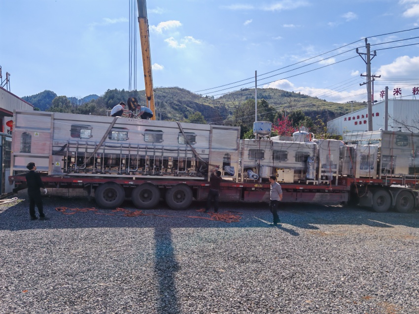
A standard electroplating pure water system consists of four main stages:
1. Pretreatment
Removes suspended solids, chlorine, and hardness to protect downstream membranes.
- Multimedia filtration – sand, anthracite, and garnet layers trap particles >10 µm
- Activated carbon filtration – removes chlorine, chloramines, and organic compounds
- Water softener (ion exchange) – exchanges calcium and magnesium for sodium, preventing scaling on RO membranes
Operational boundary: If source water has high iron (>0.3 ppm) or manganese, additional oxidation or greensand filtration may be required before carbon.
2. Reverse Osmosis (RO) – Primary Desalination
RO membranes remove 95–99% of dissolved salts, organic molecules, and colloidal matter.
- Two-stage RO is common for moderate TDS (500–1500 ppm); single-stage may suffice for low TDS
- Permeate water typically has conductivity <20 µS/cm
- Recovery rate is usually 65–75% for standard brackish water membranes; higher recovery may cause scaling
Equipment logic: The RO system is controlled by a PLC that monitors feed pressure, permeate flow, and conductivity. Automatic membrane flush cycles extend membrane life.
3. Polishing (DI or EDI)
After RO, water passes through either:
- Mixed-bed deionization (DI) – cation and anion resins in a single vessel, exchanging remaining ions for H⁺ and OH⁻. Produces resistivity up to 18.2 MΩ·cm. Requires periodic chemical regeneration (acid and caustic).
- Electrodeionization (EDI) – uses electrical current to continuously regenerate resin; no chemical regeneration needed. Output resistivity typically 10–18 MΩ·cm. More expensive upfront but lower operating cost for high-volume systems.
Selection boundary: For systems with >2000 L/h capacity and continuous operation, EDI often pays back within 2–3 years versus DI due to reduced chemical consumption and labor.
4. Storage and Distribution
Polished water is stored in a stainless steel or polyethylene tank with a UV sterilizer (254 nm) to prevent bacterial regrowth. A recirculation loop maintains constant flow and resistivity at each point-of-use.
After Adoption: Operational Boundaries and Maintenance
Once the system is commissioned, realistic expectations include:
- Membrane replacement every 3–5 years depending on feed water quality and cleaning frequency
- Resin regeneration (for DI systems) every 2–6 months – requires trained operators or a service contract
- EDI modules typically last 5–8 years before replacement
- Periodic monitoring of influent and effluent conductivity, system pressure, and flow rates
Common pitfalls:
- Under-sizing the pretreatment leads to RO membrane fouling within weeks
- Using untreated water for rinsing during maintenance shutdowns can contaminate the entire distribution loop
- Neglecting UV lamp replacement (annual) allows biofilm formation in storage tanks
Key Selection Criteria for Procurement Teams
| Factor | What to Verify |
|---|---|
| Source water analysis | Request a full lab report (TDS, hardness, iron, silica, SDI) |
| Target resistivity | Match to plating specification (e.g., 10 MΩ·cm for decorative chrome, 18 MΩ·cm for electronics) |
| Flow rate & duty cycle | Consider peak demand and future expansion; oversizing by 20% allows for growth |
| Maintenance capabilities | On-site staff vs. outsourced support; DI regeneration vs. EDI |
| Space & utilities | Floor area, drainage, power supply, and compressed air (for pneumatic valves) |
Practical Next Steps
- Collect a representative source water sample and have it tested at a certified laboratory.
- Define your quality target (resistivity/conductivity, flow rate, batch vs. continuous).
- Request a preliminary system design from a water treatment equipment manufacturer like Chuxin Mingwei that includes process flow diagram, component list, and estimated footprint.
- Evaluate total cost of ownership – include capital, installation, consumables, energy, and maintenance over 5 years.
Conclusion
Electroplating pure water systems are not one-size-fits-all. The correct configuration depends on your source water chemistry, target quality, flow demand, and operational constraints. By understanding the core stages—pretreatment, RO, polishing, and distribution—procurement teams can make informed decisions that balance capital cost, operating efficiency, and long-term reliability. A reputable manufacturer will provide a site-specific engineering proposal based on your actual water analysis and production requirements.
Why Work with Chuxin Mingwei
Huizhou Chuxin Mingwei Industrial Co., Ltd. engineers custom water treatment systems for industrial applications, including electroplating. Our team designs each system from your source water quality, target standards, and facility constraints—not from a generic template. We deliver complete solutions from design through commissioning and after-sales support.
Ready to discuss your electroplating pure water requirements? Contact our engineering team to start with a free source water evaluation and a preliminary system layout.