
Integrating Barrel-Wrap Packaging: Mechanical & Control Interface Checklist for 18.9L Lines
Integrating Barrel-Wrap Packaging: Mechanical & Control Interface Checklist for 18.9L Lines
Expanding a drinking water production facility often involves adding downstream packaging automation, such as an automatic barrel-wrap (shrink-wrapping) machine, to existing filling lines. For procurement managers and technical leads, the primary challenge is not just purchasing the new unit, but ensuring it integrates seamlessly with the current Bottled Purified Water Filling Line or spring water filling equipment. Misaligned interfaces can cause frequent jams, reduce overall equipment effectiveness (OEE), and compromise the hygiene standards required for beverage production.
This article diagnoses the critical mechanical and control interfaces that must be verified before installation. It focuses on practical implementation steps for 18.9L (5-gallon) barrel lines, drawing on standard engineering practices for industrial water treatment and packaging systems.
Myth vs. Fact: The "Plug-and-Play" Assumption
Myth: An automatic barrel-wrap machine can be placed immediately after the capping station with minimal adjustment, as long as the conveyor height matches.
Fact: While physical height alignment is necessary, it is insufficient. Successful integration requires synchronized speed control between the filling line’s exit conveyor and the wrapper’s infeed, precise sensor logic to prevent bottle collisions, and compatible PLC communication protocols. Without these, the system will either starve the wrapper (causing idle time) or flood it (causing jams).
1. Mechanical Interface: Conveyor Synchronization & Transfer Logic
The most common point of failure in line expansion is the transfer zone between the filling/capping unit and the packaging machine. For 18.9L bottled water equipment, barrels are heavy and require stable guidance.
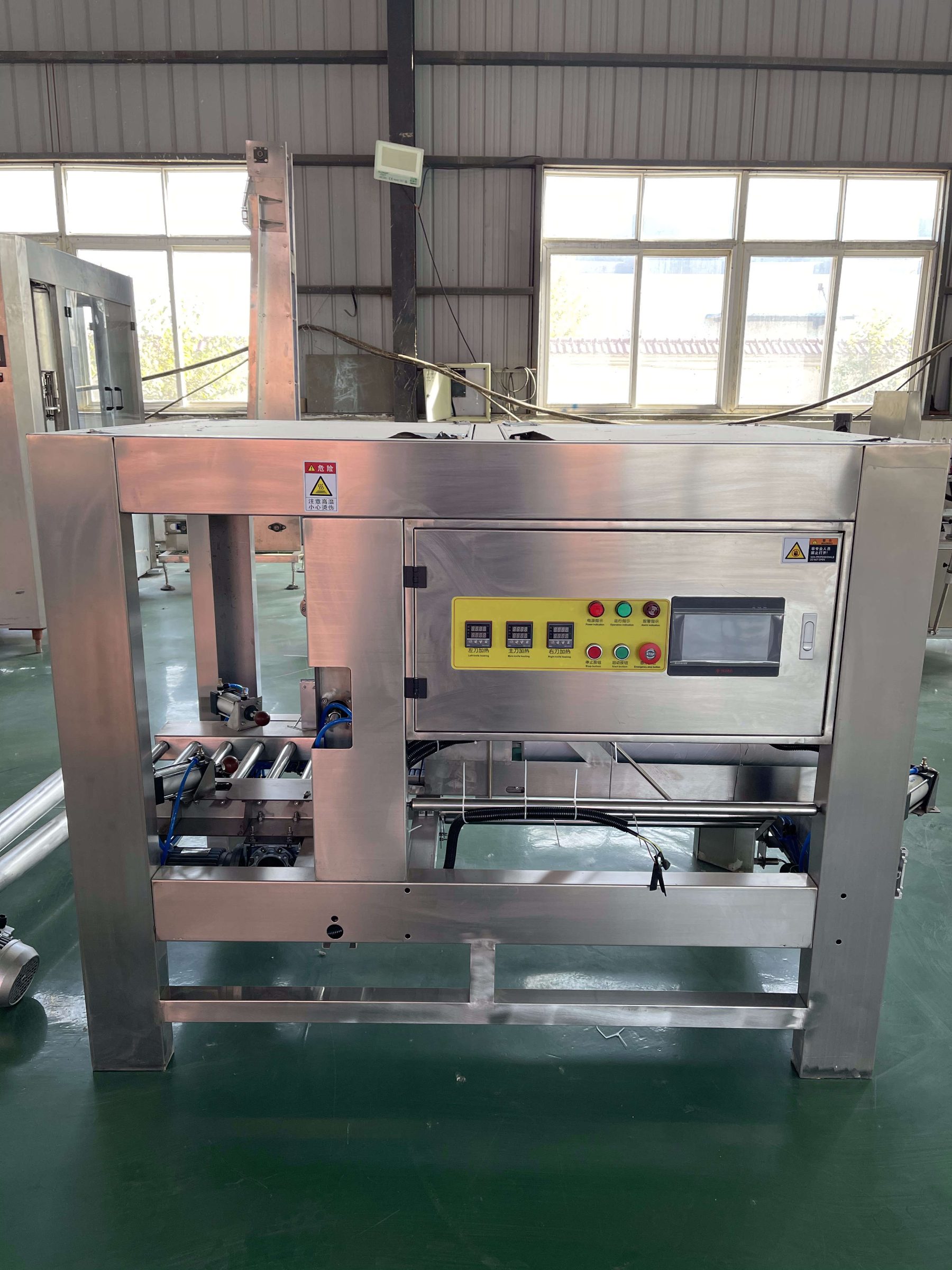
Key Checks:
- Speed Matching:*
- The exit conveyor of the filling line must operate at a variable speed that matches the input rate of the barrel-wrap machine. If the filler runs at 2,000 bottles/hour (based on Chuxin Mingwei’s capacity range for purified lines), the wrapper must handle this peak flow without accumulation pressure.
- Guide Rail Alignment:*
- Ensure the guide rails on the transfer section are adjustable to accommodate minor variations in barrel diameter. Misalignment here causes barrels to tilt, leading to jamming in the shrink tunnel.
- Accumulation Table:*
- Install a small accumulation table between the filler and wrapper. This acts as a buffer, allowing the filler to continue running briefly if the wrapper stops for film change or maintenance, thus protecting the upstream bottled spring water production line from unnecessary stoppages.
2. Control Interface: PLC Communication & Sensor Logic
Modern filling lines, such as those featuring PLC-based intelligent control systems, rely on digital handshakes to coordinate operations. Adding a new machine requires integrating its controller into the existing network.
Critical Integration Points:
- Start/Stop Handshake:*
- The wrapper should send a "Ready" signal to the filling line’s PLC. If the wrapper is down, the filling line must automatically slow down or stop to prevent overflow. Conversely, if the filler stops, the wrapper should enter a standby mode to save energy and film.
- Sensor Placement:*
- Install photoelectric sensors at the infeed of the wrapper to detect barrel presence. These sensors must be calibrated to ignore ambient light and steam from the shrink tunnel, which can cause false triggers.
- Fault Alarms:*
- Integrate the wrapper’s fault codes into the main HMI (Human-Machine Interface) of the filling line. Operators should see a unified alarm message (e.g., "Wrapper Film Low" or "Conveyor Jam") rather than having to check a separate panel on the packaging unit.
3. Utility & Environmental Boundaries
Before finalizing the layout, verify that the facility’s utilities can support the additional load. Automatic shrink-wrapping machines require significant thermal energy and compressed air.
- Power Supply:*
- Confirm that the electrical panel has sufficient capacity for the heating elements of the shrink tunnel. High-power heaters may require a dedicated circuit to avoid voltage drops that could affect sensitive industrial purification system controls.
- Compressed Air:*
- If the wrapper uses pneumatic actuators for film cutting or sealing, ensure the plant’s air supply has adequate pressure and dryness. Moisture in the air lines can lead to inconsistent seals and product waste.
- Heat Dissipation:*
- Shrink tunnels generate substantial heat. Ensure the installation area has adequate ventilation to prevent overheating of nearby electronic components or affecting the ambient temperature of the cleanroom, especially if the line is integrated with clean air purification systems designed for ISO Class 8 standards.
Implementation Steps for Technical Teams
- Site Survey: Measure the exact footprint and utility access points at the proposed installation site. Verify ceiling height for the shrink tunnel exhaust.
- Interface Definition: Draft a detailed interface document specifying conveyor widths, sensor types, PLC I/O points, and communication protocols (e.g., Modbus, Ethernet/IP).
- Dry Run: Perform a non-product test run to synchronize speeds and adjust guide rails. Use empty barrels to simulate flow and identify potential jam points.
- Operator Training: Train staff on the new interface controls, focusing on clearing jams safely and changing film rolls without disrupting the entire line.
Conclusion
Integrating an automatic barrel-wrap machine into an existing Huizhou manufacturer-supplied filling line is a manageable project when approached with a focus on interface precision. By prioritizing conveyor synchronization, robust PLC communication, and utility readiness, operations teams can achieve a seamless scale-up that maintains production stability and product quality.
For specific interface requirements tailored to your existing line configuration, please consult our engineering team. We provide end-to-end support, from design to commissioning, ensuring your expansion meets operational goals.
[Contact Our Engineering Team for a Site Assessment]
For 18.9L lines, the mechanical interface must accommodate the specific workflow of barrel processing, which typically includes recovery bucket inspection, cap removal, external brushing, internal washing and disinfection, rinsing, filling, cap sorting/pressing, lamp inspection, bagging, and conveying. The integration checklist should verify that the wrapper's infeed aligns with the final stage of this sequence, ensuring stable guidance for heavy barrels. Additionally, confirm if the line utilizes a combined washing-filling-capping unit or separate stations, as this affects the transfer logic and space requirements for the shrink-wrapping equipment.
Recommended
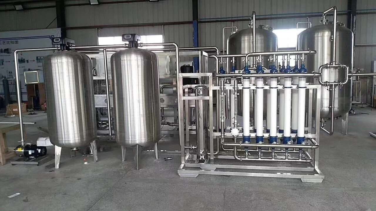
Bottled Spring Water Filling Production Line
Chuxin Mingwei’s customized bottled spring water filling production line is specifically...
Automatic Barrel-Wrap Packaging Machine for Drinking Water
A fully automated, food-grade barrel-wrapping solution engineered for bottled water prod...
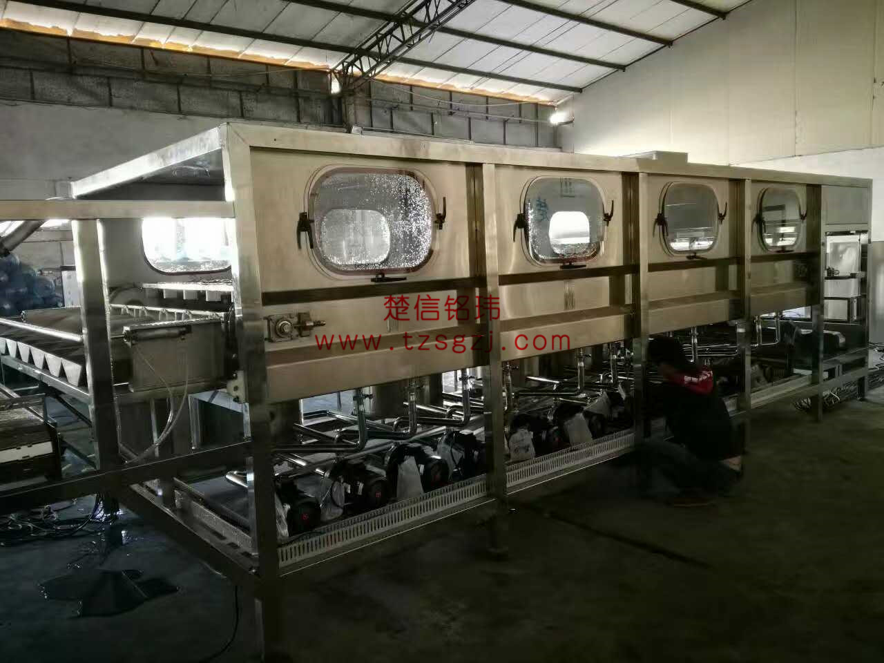
Fully Automatic Bottled Purified Water Filling Production Line
Chuxin Mingwei’s customized fully automatic bottled purified water filling production li...