
Purified Water Bottling Machine Working Principle Explained: Common RO Integration Issues and Corrective Actions
Why a “Fully Automatic” Line Can Still Go Off‑Spec
You’ve invested in a fully automatic bottled purified water filling production line, and the control panel shows all systems running. Yet the lab reports a conductivity spike in the last batch. The line is forced to stop, and thousands of bottles are held for re‑testing. The root cause is rarely the filling machine itself — it’s usually a process instability several stages upstream.
Understanding the working principle of the entire line, not just the bottling section, is the only way to prevent such silent failures. This article walks through each functional block, explains how they interact, and provides corrective actions for the most common deviations.
The Complete Purified Water Bottling Process Chain
A modern purified water bottling machine is not a single device; it’s an integrated system that spans water treatment, disinfection, storage, container handling, and filling. The typical sequence, based on the core process knowledge used by Chuxin Mingwei, is:
Raw water → Pre‑treatment → Precision filtration → RO (reverse osmosis) deionization → Disinfection → Finished water storage & circulation → Container washing → Filling & capping → Inspection → Packaging
Each step depends on the output quality of the previous one. A failure in pre‑treatment will eventually hit the RO membranes; a poorly maintained storage tank will compromise disinfection. Let’s examine each stage with a focus on operating logic and boundaries.
1. Pre‑treatment: The First Line of Defense
Raw water — whether municipal, borewell, or surface — contains suspended solids, organic matter, and hardness ions. Pre‑treatment typically includes multi‑media filtration, activated carbon filtration, and softening. Its job is to reduce turbidity, remove chlorine and organics, and prevent scale formation on the RO membranes.
When pre‑treatment is neglected, the downstream precision filter clogs prematurely, and the RO membrane feed SDI (Silt Density Index) rises beyond the acceptable limit (usually < 5). This is the most common trigger for conductivity excursions.
Corrective action: Monitor differential pressure across pre‑treatment filters daily. If the pressure drop exceeds the manufacturer’s recommendation, backwash or replace media. In areas with high hardness, ensure the softener brine tank is never empty — a simple oversight that can cost a full set of RO elements.
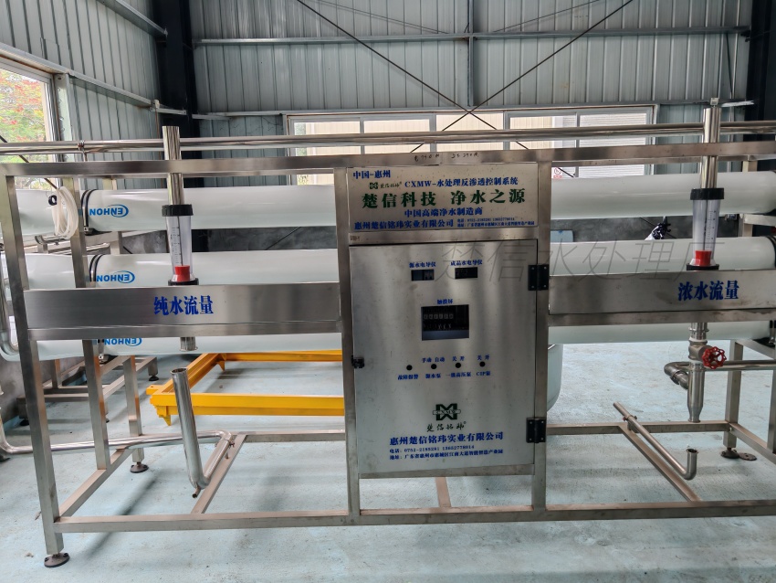
2. Two‑Stage RO Deep Purification
Once the water passes through 5‑micron precision filtration, it enters the heart of the system: the two‑stage RO unit. This is the defining feature of the fully automatic bottled purified water filling production line offered by Chuxin Mingwei. The first stage removes the bulk of dissolved salts; the second stage polishes the permeate to achieve consistent low conductivity (typically < 10 µS/cm).
Why two stages instead of one? A single‑stage RO can deliver acceptable quality under stable feed conditions, but seasonal changes in raw water temperature and TDS inevitably shift the permeate quality. A two‑stage design provides a buffer, ensuring the final water remains within specification even when feed conditions vary.
Operating logic: High‑pressure pumps, controlled by VFDs (variable frequency drives), maintain constant cross‑flow velocity. Online conductivity meters feed signals to the PLC; if permeate conductivity drifts above the setpoint, the system can divert to drain and trigger an alarm. Membrane performance is tracked by normalized permeate flow and salt rejection — not just by looking at the pressure gauges.
Common failure and correction: Gradual permeate quality decline often points to membrane fouling or scaling. Instead of blindly increasing pump pressure, check the pressure drop across each stage, the feed water temperature, and the SDI. If fouling is confirmed, perform low‑pH cleaning for inorganic scales, then alkaline cleaning for organic fouling. Reduce the cleaning interval if the problem recurs; it may indicate inadequate pre‑treatment.
3. Disinfection and Finished Water Stability
After RO, the purified water is stored in a sterile tank and circulated through a loop that includes ozone and UV (254 nm) dual sterilization. This combination addresses a critical gap: ozone provides residual disinfection and protects the tank and piping, while UV acts as a final barrier against any micro‑organisms that might have entered after the tank.
Unlike chlorine, ozone leaves no taste and decomposes quickly, but it requires careful control. Too little ozone, and the distribution system loses protection; too much, and off‑gassing can create a health hazard and affect bottle material. The system must include an ozone destruction unit for vented air.
Corrective action: Verify the ozone generator output and the UV lamp intensity monthly. If the UV sensor reading drops below 70 % of the new lamp value, replace the lamp. If the ozone residual at the filler inlet is below the target (typically 0.3–0.5 ppm), check the injector and contact tank.
4. Container Washing and the 3‑in‑1 Filling Machine
Up to this point, the system has produced high‑quality water. Now it must be transferred into bottles without re‑contamination. The bottle washing‑filling‑capping monoblock, often called a 3‑in‑1 machine, is the most visible piece of equipment. It rinses the bottle, fills it to a precise volume, and caps it — all in a controlled, enclosed environment.
For new PET bottles, the washing stage uses the same purified water to flush out any dust or particles. The filling is typically gravity‑based or pressure‑based, with a filling accuracy of ≤ ±2 mL for a 5‑gallon (18.9 L) bottle. The capping head applies a pre‑sanitized cap with a torque that ensures a leak‑proof seal without damaging the neck.
Why does a bottle that was filled acceptably in the morning fail inspection in the afternoon? The most common cause is a change in bottle shape or thickness due to warm storage, which affects the capping torque. Another is a worn sealing gasket on the filling valve, leading to inconsistent fill levels. Routine checks of the capping head torque and fill valve gaskets, combined with a torque tester, can prevent these issues from cascading into a production stop.
5. Inspection and Final Packaging
After capping, bottles pass through a light inspection station where an operator (or camera system) checks for visible particles, fill level, and cap placement. A missing cap or low fill triggers an automatic rejection. The bottles then move to labeling, shrink wrapping, coding, and palletizing.
System Boundaries: What the Machine Relies On
Understanding the working principle also means knowing what the filling line cannot do on its own. The system’s performance depends on:
- Raw water quality report:*
- Without a full analysis, pre‑treatment design is guesswork.
- Stable power supply:*
- VFDs and PLCs are sensitive to voltage fluctuations and harmonics.
- Compressed air quality:*
- The 3‑in‑1 machine uses instrument‑grade air for valve actuation; oil or moisture in the air will contaminate the product.
- Room cleanliness:*
- The filling area must maintain at least ISO Class 8 (100,000) cleanliness; otherwise, the bottling process itself becomes a source of contamination.
Chuxin Mingwei’s engineering approach is to design the complete line — including water treatment, clean air systems, and the filling equipment — as a single process, not as separate pieces. This is the only way to define clear responsibility boundaries and avoid gaps during commissioning.
When to Call for Engineering Support
If you observe any of the following, it’s time to involve the equipment manufacturer:
- Conductivity re‑work rate exceeds 2 % of daily production.
- RO membrane cleaning frequency is less than every 3 months.
- Capping pass rate drops below 99.6 %.
- Ozone residual cannot be maintained within the target window.
Small adjustments can often be made by the plant team, but systemic issues almost always point to a mismatch between the original design assumptions and the actual operating conditions — something that requires a site‑specific review.
For a detailed discussion of your water quality, production capacity, and packaging format, contact Chuxin Mingwei’s engineering team. They can help you map the right process chain and avoid the hidden failure points that stop production.